The 3-point bending test machine stands as a critical tool in material testing, enabling engineers and researchers to assess the mechanical properties of materials under flexural stress. This blog post serves as a detailed guide to understanding the fundamental principles, technical workings, and practical applications of this widely utilized testing method. From evaluating material stiffness to identifying yield points and fracture limits, the 3-point bending test provides invaluable insights into material performance across a broad spectrum of industries, including construction, aerospace, and automotive manufacturing. By the end of this article, readers will gain a thorough understanding of how the 3-point bending test operates, why it is essential in quality control and material development, and the key considerations for accurate and reliable testing results. Whether you’re a seasoned professional or new to material testing, this comprehensive guide will equip you with the knowledge to better interpret and apply the outcomes of bend testing.
What is a 3 point bending test machine and How Does it Work?
A 3-point bending test machine is a device used to evaluate the strength, flexibility, and fracture behavior of materials by applying a load at a single central point on a specimen supported at two ends. The test operates by placing the material sample on two fixed supports and then exerting a downward force through a loading nose at the midpoint of the span. This setup creates a bending moment that subjects the material to both tensile and compressive stresses. The machine records the applied load and the corresponding deflection to determine key properties such as flexural strength, modulus of elasticity, and fracture characteristics. This method is widely used for testing materials like metals, plastics, ceramics, and composites.
Principles of the 3-Point Bend Test
The 3-point bend test operates on principles of applied mechanics to determine material properties like flexural strength, modulus of elasticity, and flexural strain. A specimen is typically supported at two points (spanning a specific support distance) while a single concentrated force is applied perpendicularly at the midpoint. This setup generates a bending moment, creating tensile stress on the material’s underside and compressive stress on the top. By measuring parameters such as force and deflection during the test, a stress-strain curve is generated, enabling precise calculation of the material’s mechanical responses. This method is particularly valuable for testing brittle materials, such as ceramics or composites, to assess their behavior under flexural stresses.
Components and Setup of a 3-Point Bend Test Machine
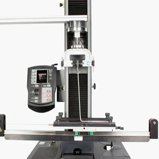
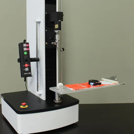
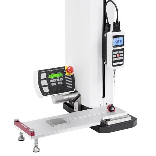
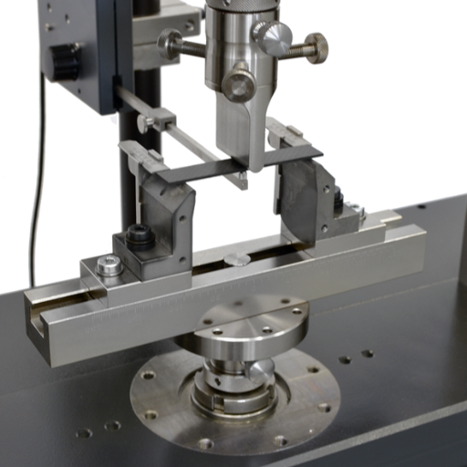
The 3-point bend test machine typically consists of the following key components and setup arrangements, designed to produce accurate and reliable mechanical data for material analysis:
- Load Cell
The load cell is a critical component responsible for measuring the applied force during the test. Its high sensitivity ensures precise force measurement, which is essential for generating accurate stress-strain curves. Load cells can vary in capacity depending on the test requirements, ranging from a few Newtons to several kilonewtons.
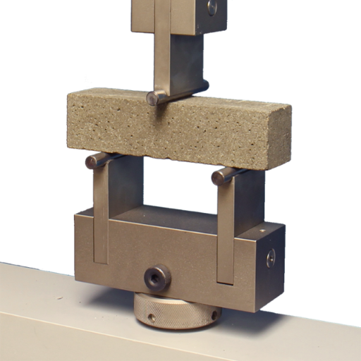
- Support Fixture
The support fixture consists of two parallel lower supports that hold the material specimen in place. These supports are usually adjustable to accommodate specimens of varying lengths and are engineered with precise geometry to minimize errors due to misalignment or uneven loading. The span length between the supports is a key variable in the test configuration.
- Loading Nose (Central Anvil or Plunger)
The loading nose is the upper fixture that applies force to the midpoint of the specimen. It is designed with a rounded or cylindrical surface to ensure a uniform distribution of stress on the specimen during deflection. The position of the loading nose is carefully controlled to maintain the proper alignment throughout the test.
- Specimen
The test specimen is typically a rectangular or cylindrical bar, machined to specific dimensions according to standardized protocols, such as ASTM D790 or ISO 178. The specimen’s geometry, including thickness, width, and span-to-depth ratio, directly influences the test results, making precise preparation critical.
- Displacement Sensor
A displacement sensor, such as a linear variable differential transformer (LVDT), is used to measure the deflection of the specimen at the point of applied load. The resolution and response time of the sensor play a crucial role in capturing accurate deformation data in real time.
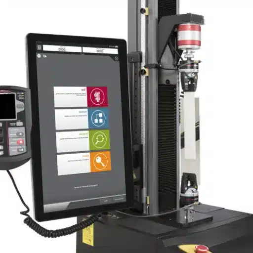
- Controller and Software
The test machine is typically operated via a computer-controlled system equipped with dedicated software. This system automates the application of force, records real-time data, and calculates corresponding parameters like stress, strain, and modulus of elasticity. Advanced software also allows for visualization of the stress-strain curve and post-test analysis.
Setup Process
- Specimen Preparation
Ensure the specimen is prepared according to the required standards. Verify its dimensions, surface finish, and orientation meet the specified criteria.
- Fixture Adjustment
Position the support fixtures to achieve the correct span length for the test. Secure the specimen on the supports such that its central axis aligns precisely with the loading nose.
- Calibration
Calibrate the load cell and displacement sensor to ensure accuracy in force and deflection measurements. This step minimizes systemic errors and improves test reliability.
- Test Configuration
Input the required parameters into the software, including test speed, maximum force limit, and stop conditions. Ensure the alignment of all components to avoid deviations during testing.
- Execution and Data Collection
Start the test. The loading nose applies a controlled force at a constant rate, displacing the specimen while the load cell and displacement sensor record force and deflection data. This data is used to generate the resulting stress-strain curve.
The proper configuration and calibration of these components ensure the 3-point bend test delivers highly accurate and reproducible mechanical properties, such as flexural strength, modulus of elasticity, and material toughness.
Key Differences Between 3-Point and 4-point bending test machine
The key differences between 3-point and 4-point bending test machines lie in the loading configuration, stress distribution, precision in material property evaluation, and the locations where maximum bending stresses occur.
|
Key Point |
3-Point Test |
4-Point Test |
|---|---|---|
|
Load Points |
Single central point |
Two evenly spaced points |
|
Stress Zone |
Maximum stress at one point |
Uniform stress between points |
|
Precision |
General material testing |
High precision for composites |
|
Applications |
Basic material evaluation |
Advanced structural analysis |
|
Setup Complexity |
Simple |
Moderate |
|
Failure Location |
Central point |
Anywhere within load zone |
|
Stress Type |
High concentration |
More distributed |
|
Result Stability |
Moderate |
High |
|
Flexural Strength |
Directly determined |
Averaged over larger region |
|
Support Setup |
Two supports |
Two supports, wider span |
How to Conduct a Three Point Bend Test Using the Right Fixture
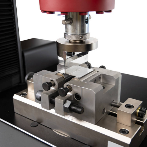
To perform a three-point bend test, begin by selecting the appropriate fixture and test setup based on the material and structural analysis requirements. Secure the specimen between two support points at a predefined span, ensuring proper alignment to prevent torsion. Apply a concentrated load at the central point of the specimen using the loading nose with uniform displacement or force rate. Monitor load and displacement data through the testing system for accurate measurement of material properties such as flexural strength and stiffness. Ensure all parameters, such as span length and loading rate, comply with relevant testing standards (e.g., ASTM or ISO). Following the test, analyze the fracture location and the stress distribution to interpret results effectively.
Choosing the Correct Test Fixture for Your Specimen
When selecting the appropriate test fixture for my specimen, I consider several critical factors to ensure precision and compliance with testing standards. First, I examine the dimensions, shape, and material properties of the specimen to determine the fixture’s compatibility. Next, I evaluate the type of test being conducted—whether it is tensile, compression, flexural, or shear testing—to ensure the fixture design meets the specific mechanical requirements and loading conditions.
I also review the load capacity and alignment features of the fixture to prevent potential misalignment or overloading that could compromise the results. Additionally, I verify that the fixture adheres to relevant standards (such as ASTM or ISO) to maintain consistency and accuracy in the test procedure. Finally, I cross-reference the fixture’s specifications with my testing equipment to confirm compatibility and proper integration.
Step-by-Step Guide to Performing a Point Bend Test
- Prepare the Specimen
Select a specimen that meets the required dimensions and material specifications for the test. Inspect the specimen for any surface defects or inconsistencies that could affect the accuracy of the results. Ensure the specimen is clean and free from any debris or contaminants.
- Calibrate the Testing Machine
Confirm that the testing machine has been properly calibrated according to the relevant standards. Verify the calibration records and perform any necessary adjustments to ensure the equipment provides accurate force and displacement readings.
- Install the Testing Fixture
Securely attach the appropriate point bend fixture to the testing machine. Confirm that the fixture is aligned and positioned according to the test setup requirements. Check for proper clearance and alignment to avoid stress concentrations or uneven loading.
- Position the Specimen
Place the specimen on the fixture supports, ensuring the correct orientation and positioning according to test specifications. Align the specimen so the force will be applied at the designated point of loading.
- Set Test Parameters
Input the necessary test parameters, including loading rate, maximum force, and displacement limits, into the control system of the testing machine. Ensure that all parameters comply with the governing standards and the purpose of the test.
- Conduct the Test
Initiate the testing process by applying the load at the pre-determined rate. Monitor the force-displacement curve in real time and observe the specimen’s response until failure or until the desired load or displacement is achieved.
- Record the Data
Collect and save all relevant data, including the applied force, displacement, and any observed deformations or fractures. Ensure that the data acquisition system is functioning properly and capturing accurate measurements.
- Analyze the Results
Review the recorded data to calculate key performance metrics such as flexural strength, yield point, and modulus of elasticity. Cross-check the results with the test objective and any baseline data or standards.
- Clean and Inspect Equipment
After the test is completed, clean the fixture and testing machine to remove any debris or residue. Inspect the equipment for signs of wear or damage to ensure it remains in optimal working condition.
- Document and Report Findings
Compile the analysis and observations into a detailed report. Include all relevant data, test parameters, and any deviations observed during the process. Ensure the report adheres to the required format and standards for record-keeping and communication.
Common Errors to Avoid During Three Point Bend Tests
- Improper Alignment of the Specimen
Misalignment of the test specimen in the fixture can lead to inaccurate results. The specimen must be positioned symmetrically with respect to the load application point to ensure uniform force distribution. Verify alignment to minimize test artifacts caused by uneven loading.
- Incorrect Support Span Length
Using a support span length that does not conform to standard testing parameters (e.g., a ratio of span-to-depth often recommended as 16:1) can skew flexural strength calculations. Always refer to ASTM D790 or ISO 178 standards for precise span-to-depth ratios based on the specimen dimensions.
- Exceeding the Load Cell Capacity
Applying force beyond the specified capacity of the load cell can damage equipment and generate invalid data. Ensure the load cell capacity exceeds the required maximum force, typically calculated based on the estimated yield strength and cross-sectional area of the specimen.
- Improper Strain Rate Application
Applying an inconsistent or non-standard strain rate can alter the mechanical response. For polymer testing, commonly recommended strain rates range between 1–10 mm/min depending on the material type and standard guidelines. Maintain precise control over the crosshead speed to avoid statistical deviations.
- Surface Defects or Residual Stresses in the Specimen
Specimens with scratches, voids, or residual machining stresses can exhibit premature failure. Use high-quality specimens prepared per standard cutting or molding processes to ensure test validity. Inspect the specimens thoroughly before testing.
- Environmental Factors
Variations in temperature or humidity can affect material properties, particularly for polymers and composites. Conduct testing in a controlled environment, commonly at standard laboratory conditions of 23°C ± 2°C and 50% ± 5% relative humidity, or as specified by the applicable standard.
By avoiding these errors and adhering rigorously to established standards, accurate and repeatable results can be achieved during three point bend tests.
Why ASTM Standards Matter in Point Bend Testing
Adhering to ASTM standards in point bend testing ensures consistency, reliability, and comparability of results across different laboratories and applications. These standards define critical parameters such as specimen dimensions, loading rates, and environmental conditions, minimizing variability and potential errors. By following ASTM guidelines, engineers, researchers, and technicians can trust the validity of data used for material selection, quality control, and structural analysis. This uniformity is essential for predicting material performance and ensuring compliance with industry requirements.
Overview of ASTM D790 and Its Importance
ASTM D790 is a widely recognized standard for determining the flexural properties of unreinforced and reinforced plastics, as well as electrical insulating materials. It specifies the procedure for conducting a three-point bending test to evaluate parameters such as flexural strength, flexural modulus, and strain at break. This standard is vital for assessing a material’s mechanical behavior under bending loads, offering critical data for applications where flexural performance is a key design consideration. By adhering to ASTM D790, manufacturers and engineers ensure consistent quality control, validate design criteria, and meet regulatory compliance, ultimately enhancing the reliability and safety of their products.
Comparing ASTM Standards with ISO for Bend Testing
ASTM and ISO standards for bend testing differ in testing methods, specimen dimensions, and calculation formulas.
|
Parameter |
ASTM |
ISO |
|---|---|---|
|
Scope |
Flexural tests |
Bending tests |
|
Method |
D790 |
178 |
|
Unit |
Imperial |
Metric |
|
Formula |
Defined in D790 |
Specified in 178 |
|
Specimen |
3-point bend |
3/4-point bend |
|
Parameters |
Strength, modulus |
Strength, offset |
|
Application |
US industries |
Global standards |
|
Compliance |
ASTM-specific |
ISO-specific |
Ensuring Compliance with Standard Test Methods
Ensuring compliance with standard test methods requires a systematic approach that begins with understanding the specific requirements laid out by the relevant standards, such as ASTM D790 and ISO 178. I ensure that all test procedures strictly adhere to the outlined methods, such as specimen preparation, dimensional tolerances, and loading rates. Additionally, I consistently calibrate and validate testing equipment to meet the prescribed specifications. By cross-referencing the standards’ documentation and maintaining updated records, I can verify that all tests meet both ASTM and ISO compliance while ensuring accurate and reliable results.
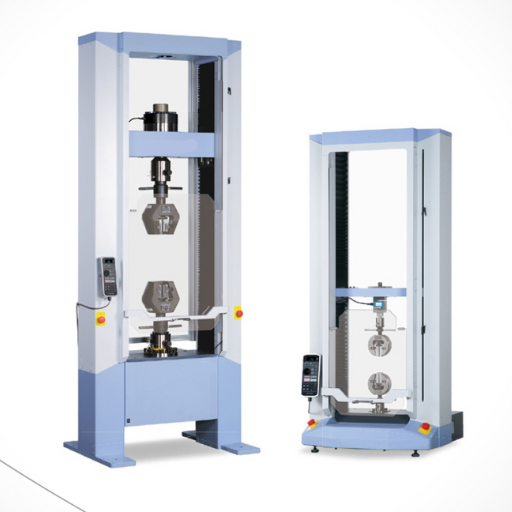
Exploring the Role of Universal Testing Machines in Flexural Testing
Universal Testing Machines (UTMs) play a critical role in the accurate performance of flexural testing by providing precise control over loading parameters and ensuring compliance with standardized testing protocols. These machines are designed to apply a controlled force or displacement to a material specimen while continuously monitoring the load-deflection response. Equipped with advanced sensors and software, UTMs enable the calculation of key material properties such as flexural strength, modulus of elasticity, and strain at failure. Their versatility allows for the integration of various fixtures to accommodate different specimen geometries and testing standards, making them indispensable tools in material characterization and quality assurance workflows.
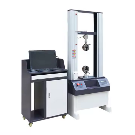
Advantages of Using a Universal Testing Machine
- Versatility in Testing Applications – Universal Testing Machines are capable of performing a wide range of tests, including tension, compression, bending, and shear, making them suitable for evaluating diverse material properties across various industries.
- High Precision and Accuracy – Equipped with precision load cells and extensometers, UTMs ensure accurate measurements of forces, displacements, and material properties, adhering to stringent industry standards.
- Compatibility with Multiple Standards – UTMs are designed to comply with international testing standards such as ASTM, ISO, and EN, ensuring global consistency and reliability of test results.
- Advanced Data Acquisition and Analysis – Modern UTMs feature integrated software systems for real-time data collection, graphical representation, and sophisticated analysis, enabling comprehensive evaluation of material behavior.
- Customization and Adaptability – With interchangeable fixtures, grips, and extensometers, UTMs can be tailored to suit specific testing needs, accommodating a variety of specimen sizes and shapes.
How to Calibrate a Universal Testing Machine for Bend Tests
- Inspect and Prepare the Machine
First, I ensure the Universal Testing Machine (UTM) is clean, free from debris, and all components are properly aligned. I also verify that the machine’s fixtures and accessories, such as bending supports and loading noses, are appropriate for the test specifications.
- Review Calibration Standards
I consult the relevant standards, such as ASTM E290 or ISO 7438, to confirm the calibration and testing requirements, including the acceptable tolerances and load cell accuracy.
- Verify Load Cell Accuracy
Using certified calibration weights or a load verification device, I check the load cell to ensure it provides precise and linear force measurements across the expected test range.
- Calibrate Displacement Measurement Devices
I confirm the accuracy of the extensometers or displacement transducers by comparing their readings with a traceable standard or precision gauge.
- Perform a Trial Run
Finally, I conduct a simulated bend test on a calibration block or dummy specimen to double-check the alignment, load application, and measurement systems. Any discrepancies are adjusted before proceeding with actual tests.
By following these steps, I ensure that the UTM operates within specified parameters, delivering reliable and repeatable results for bend testing.
What are the Key Applications of Three-Point Bend Tests in Material Testing?
Three-point bend tests are commonly used to assess the mechanical characteristics of materials subjected to flexural stress. The primary objectives of these tests are to measure flexural strength and calculate the materials’ modulus of elasticity and fracture toughness. They are especially useful in evaluating the performance of polymers, composites, and metals in aerospace, automotive, and construction applications. Moreover, these tests are important in quality assurance and research since they provide vital information needed for material choosing and design refinement.
Assessing Flexural Properties of Plastics and Composites
The flexural properties of plastics and composites are typically assessed through standardized testing methods such as ASTM D790 or ISO 178. These involve subjecting a specimen to three-point or four-point bending, during which the flexural strength, modulus, and strain are calculated. These parameters provide insights into the material’s ability to resist deformation under load. Plastics often exhibit viscoelastic behavior, influencing their performance under flexural stress, while composites demonstrate anisotropic properties, meaning their strength and stiffness vary depending on the direction of the applied force. Proper evaluation is essential for applications in structural components, ensuring that the material meets specific design and performance requirements.
Measuring Flexural Modulus and Strength
The flexural modulus is determined by subjecting a material to a bending test, where a sample is placed on two supports while a force is applied at its center. This test measures the material’s stiffness and resistance to bending under load, providing a key metric for structural performance. Commonly, the three-point or four-point bending test configurations are utilized, adhering to standardized methods like ASTM D790 or ISO 178. The stress-strain data collected during the test is used to calculate the flexural modulus and strength, with the modulus derived from the slope of the stress-strain curve in the elastic region.
For flexural strength, the maximum stress a material can withstand before failure occurs is measured. This value is critical in determining the suitability of materials for structural applications, ensuring they can endure operational stresses without deformation or fracture. Accurate specimen preparation, such as maintaining precise dimensions and avoiding defects, is essential for reliable results. These tests enable engineers and manufacturers to make informed decisions on material selection and design optimization in industries ranging from aerospace to consumer products.
Understanding Fracture Toughness Through Bend Testing
To address the questions regarding fracture toughness and bend testing, I will provide concise answers based on authoritative sources and technical understanding. Fracture toughness is a critical material property that quantifies a material’s ability to resist crack propagation under stress. Bend testing is an effective method for assessing this property, especially in brittle materials, by applying a controlled bending force to a specimen until it fractures. This test provides insight into stress intensity factors and the energy required to propagate a crack, enabling engineers to predict material behavior under real-world loading conditions.
The bend test setup typically involves a three-point or four-point loading arrangement, which ensures an even and measurable distribution of stress across the sample. Key variables such as the specimen’s thickness, notch dimensions, and loading rate must adhere to standardized guidelines like ASTM E399 or ISO 12135 to ensure accurate and repeatable results. By analyzing the fracture surface and recorded data, such as the maximum stress and displacement, we can determine a material’s fracture toughness and use this information to inform material selection and structural design, ensuring safety and efficiency in engineering applications.
Reference Sources
-
A Complete Guide to the Three-Point Bending Flexural Test – This guide explains the process and purpose of the three-point bending flexural test.
-
Three-point bending test (ETH Zurich) – A detailed document from ETH Zurich on performing the test using a universal testing machine.
-
Bend Testing Equipment Guide – This guide covers the equipment used for bend testing, including universal testing machines and their applications.
-
Comprehensive Guide to the Flexural Bending Test – A resource focusing on the flexural properties of materials like thermoplastics and composites.
-
Bend Testing – TWI – An overview of bend testing, its applications, and its role in evaluating material ductility and soundness.
Frequently Asked Questions (FAQs)
Q: What is a 3 point bending test machine?
A: A 3 point bending test machine is a type of test equipment used to determine the flexural properties of materials by using a point bend test fixture. It involves applying a load at a single point on a beam supported at two points, commonly used to assess the strength and deformation behavior of materials.
Q: How is a 3 point bending test performed?
A: The test is performed by placing a beam on two supports and applying a load at the midpoint using a point bend test fixture. This setup helps in determining the material’s flexural strength and elastic modulus by measuring how much the beam bends under the load.
Q: What materials can be tested using a 3 point bending test machine?
A: The 3 point bending test machine can be used to test a variety of materials, including composite materials, plastics and electrical insulating materials, reinforced plastics, and samples of metals to determine their flexural properties.
Q: What is the difference between 3 point and 4 point bending tests?
A: In a 3 point bending test, the load is applied at a single midpoint, while in a 4 point bending test, two loads are applied at equal distances from the supports. The 4 point test is typically used when more uniform stress distribution is needed across the tested section.
Q: Why is tensile strength important in relation to bending tests?
A: The tensile strength of a material remains an essential consideration in bending tests since it depicts the maximum limit of force applied to it in stretching or pulling during failure. Such data is vital for assessing the material’s ability to bend under load.
Q: What is ASTM C1161 and its relation with the bend test?
A: ASTM C1161 is a standard test method for flexural strength of advanced ceramics at ambient temperature. It describes the use of three-point bending tests to evaluate the strength and reliability of ceramic materials under flexural stresses.
Q: How is the flexure fixture used in a 3 point bending test?
A: The flexure fixture is used to securely position the beam on the supports and apply the load accurately during the test. It ensures consistent test conditions and reliable measurement of the material’s flexural properties.
Q: What role does the tensile tester play in bend testing?
A: A tensile tester, such as an Instron machine, can be used in bend testing to apply controlled loads and measure the deformation of materials. It helps in accurately determining the flexural properties and tensile strength of the tested samples.
Q: What is the typical load capacity for a 3 point bending test machine?
A: The load capacity of a 3 point bending test machine can vary, but machines with capacities such as 2kN are commonly used for testing smaller samples or materials that do not require high loads. Larger machines are available for testing stronger materials.