Universal Testing Machines (UTMs) are indispensable tools in the field of materials testing, providing precise and reliable insights into the mechanical properties of various materials. Whether you’re assessing the tensile strength of steel, the compression resistance of concrete, or the elasticity of polymers, a UTM serves as a vital component in quality control, research, and development across multiple industries. This article will explore the core functions and applications of a UTM, detailing its role in ensuring the durability and reliability of materials used in engineering, construction, and manufacturing. By the end, you’ll have a comprehensive understanding of how UTMs operate and why they are critical for maintaining safety and performance standards in countless applications.
How Does a Universal Testing Machine Work?
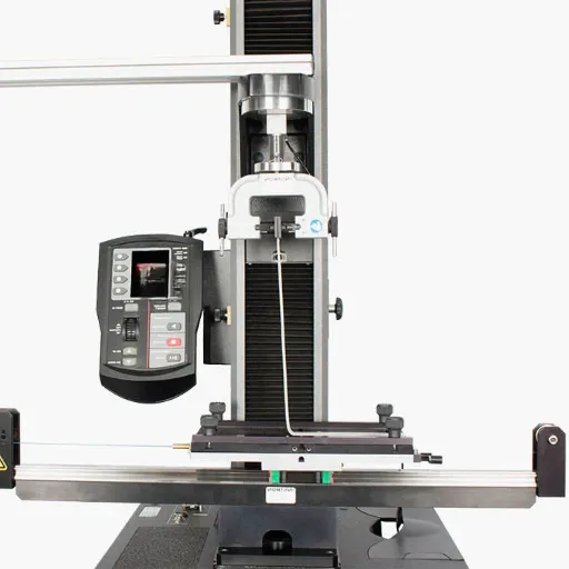
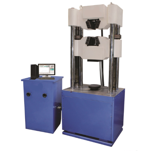
A Universal Testing Machine (UTM) operates by applying controlled forces to a material specimen to evaluate its mechanical properties. The machine consists of two key components: a loading frame and a control console. The loading frame holds the specimen securely between its upper and lower fixtures, while the control console manages the application of load or displacement.
Tests typically involve applying tensile, compressive, or flexural forces to the specimen. Sensors within the UTM measure critical parameters such as force, deformation, and elongation, which are recorded and processed for analysis. These measurements provide insights into a material’s strength, elasticity, and overall performance, making the UTM indispensable for quality assurance and mechanical testing.
What Is A universal Testing Machine and How Is It Used?
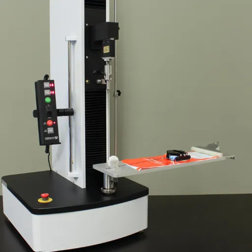
A Universal Testing Machine (UTM) is a versatile piece of equipment designed to evaluate the mechanical properties of materials under varying load conditions. It operates by subjecting test specimens to tensile, compressive, or bending forces, generating accurate data on material behavior. Modern UTMs are equipped with advanced sensors and software, enabling precise measurement of force, displacement, stress, and strain. These machines play a pivotal role in industries such as construction, aerospace, and manufacturing by ensuring compliance with safety standards and material specifications.
The operation of a UTM follows a systematic approach. The specimen is firmly secured between two clamps or fixtures designed based on the type of test being conducted. Through hydraulic or electromechanical systems, controlled forces are applied while real-time data is collected. This data is then analyzed to determine critical properties, including yield strength, ultimate tensile strength, and elasticity modulus. Additionally, the latest advancements in sensor technology and integration with computational tools allow UTMs to deliver highly detailed and reliable results, streamlining the material testing process and aiding in research, quality control, and product development.
How Does the Machine Operate to Perform Tests?
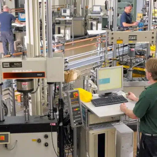
To perform tests, a universal testing machine (UTM) employs a combination of advanced mechanical and electronic systems. First, the specimen is securely mounted in the machine’s grips or fixtures, ensuring proper alignment to prevent eccentric loading. The machine then applies a controlled force or displacement through its load frame, which consists of either a screw-driven or hydraulic system. Simultaneously, sensors and load cells measure parameters such as force, elongation, and displacement with precision. This data is continuously captured by integrated software that processes the information in real time, generating accurate stress-strain curves and key material properties like tensile strength and elasticity. Automation and programmable test configurations enhance versatility, allowing the machine to perform a wide range of standardized tests efficiently.
What Are the Key Components of a UTM?
Key Components of a UTM
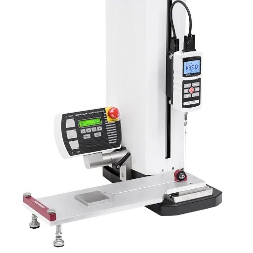
A Universal Testing Machine (UTM) comprises several critical components, each designed to ensure accurate and reliable testing of material properties. Below is a concise overview of these components along with their technical roles:
1. Load Frame
-
- The load frame provides the structural support for the entire UTM. It is designed to handle high mechanical stress and maintain rigidity during testing. Common load capacities range from 1 kN to 3,000 kN, depending on the machine’s application.
- Crosshead
- The crosshead is the movable component of the machine that applies the load to the test specimen. It can be adjusted electronically or mechanically, supporting both tensile and compressive testing.
- Load Cell
- This highly sensitive instrument measures the force applied to the test specimen with high precision, influencing the accuracy of stress-strain calculations. Load cells typically offer measurement resolutions down to ±0.5% of the applied load.
- Actuator or Drive System
- The actuator, often powered by a hydraulic or servo-electric mechanism, controls the movement of the crosshead, ensuring smooth application of force. This component defines the machine’s speed and force application precision.
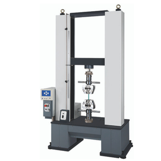
- Grips and Fixtures
- These hold the test specimen securely during testing. Different grip designs (e.g., wedge, hydraulic, or screw-action) accommodate various specimen shapes and materials, minimizing slippage or damage.
- Extensometer
- An extensometer measures specific strain by tracking elongation or deformation in the specimen. Precision levels of ±1 micrometer can be achieved, ensuring accurate determination of elongation and Young’s modulus.
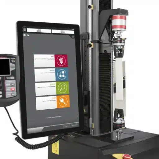
- Control System and Software
- Modern UTMs include integrated software that controls test parameters such as load rate, displacement, and duration while capturing real-time data. It facilitates automated testing and generates detailed reports.
- Safety Mechanisms
- Safety features such as overload protection, emergency stop buttons, and specimen alignment guides prevent equipment or specimen damage and ensure user safety during operation.
These components collectively ensure that UTMs provide highly reliable and precise measurements across a wide range of materials and testing scenarios.
What Types of Material Testing Can Be Performed on a UTM?
Universal Testing Machines (UTMs) are versatile devices capable of performing multiple types of material testing, including but not limited to:
1. Tensile Testing
-
- Measures the maximum tensile strength and elongation of materials by applying a uniaxial tensile force until failure.
- Compression Testing
- Evaluates a material’s behavior under compressive loads, determining properties such as compressive strength and modulus.
- Flexural Testing
- Assesses the flexural strength and stiffness of materials by applying a bending load.
- Shear Testing
- Determines a material’s shear strength by subjecting it to forces that cause sliding failure along a plane.
- Hardness Testing
- Measures surface hardness using various methods such as Brinell, Rockwell, or Vickers hardness tests.
- Peel, Adhesion, and Bond Strength Testing
- Evaluates the strength of adhesive bonds, coatings, or lamination under controlled peeling or tension forces.
These tests make UTMs invaluable tools in research, development, and quality control across industries such as construction, automotive, aerospace, and manufacturing.
Exploring Tensile Testing: Procedure and Applications
Tensile testing is a fundamental mechanical test performed to evaluate a material’s strength, deformation behavior, and elongation when subjected to uniaxial tensile forces. This test is critical for understanding how materials perform under load and for assessing properties such as tensile strength, yield strength, and ultimate elongation.
Procedure:
1. Specimen Preparation: The test begins with preparing a standardized sample, typically shaped as a dog bone or cylindrical specimen, per applicable standards (e.g., ASTM, ISO). The material and dimensions are selected based on the application and test requirements.
- Mounting in the UTM: The prepared sample is secured in the grips of a universal testing machine (UTM) to ensure alignment during testing.
- Application of Load: A controlled tensile force is applied progressively at a constant strain rate, while stress-strain data is recorded in real time.
- Measurement and Data Collection:
- Load and elongation are measured continuously using integrated load cells and extensometers.
- The test concludes when the specimen fractures or reaches failure.
- Analysis:
- The stress-strain curve is analyzed to determine key mechanical properties including yield strength, ultimate tensile strength (UTS), Young’s modulus, and breaking strain.
Applications:
1. Material Characterization:
-
- Tensile testing provides essential data on the mechanical properties of metals, polymers, composites, and textiles, aiding in material selection and design optimization.
- Quality Assurance:
- It is widely used in industry to verify that materials meet required specifications and comply with regulatory standards before deployment.
- Research and Development:
- Engineers and scientists utilize tensile testing to develop new materials, improve formulations, and simulate real-world performance.
- Failure Analysis:
- Post-failure tensile testing offers critical insights into material defects, improper processing, or design flaws, enabling corrective actions.
By serving as a comprehensive method to evaluate material strength and reliability, tensile testing remains indispensable across industries such as aerospace, automotive, construction, and medical device manufacturing.
Understanding Compression Testing and Its Uses
Compression testing is a mechanical testing method used to determine the behavior of materials under compressive forces. This process enables the evaluation of critical material properties such as compressive strength, modulus of elasticity in compression, yield strength in compression, and deformation characteristics. It is particularly useful in assessing materials intended for structural applications where load-bearing capacity is essential.
Key technical parameters for compression testing include:
1. Compressive Strength:
-
- The maximum stress a material can withstand under a compressive load before failure. Units are typically measured in megapascals (MPa) or pounds per square inch (psi).
- Modulus of Elasticity in Compression:
- Indicates the stiffness of the material while it is subjected to compressive forces. It is calculated from the linear portion of the stress-strain curve and is expressed in gigapascals (GPa) or millions of pounds per square inch (MSI).
- Yield Strength in Compression:
- Defines the stress at which a material begins to deform plastically under compressive loading. It ensures the material remains within the elastic limit for intended applications.
- Deformation Behavior:
- Assesses how the material changes in shape or size under compression, including measures such as strain and displacement.
Compression testing is widely applicable across various sectors, including construction (e.g., testing concrete and masonry), aerospace (e.g., foam core materials), and manufacturing (e.g., plastic and composite materials). By offering quantitative data on material performance under compressive loads, compression testing ensures safety, reliability, and design accuracy in engineering applications.
How Is a Flexural Test Conducted?
To conduct a flexural test, I begin by preparing the specimen according to the relevant standards, typically ensuring it is rectangular and free of defects. Next, I position the specimen on two supports within the testing apparatus, setting the span length based on the material specifications. A force is then applied at a controlled rate, either at the center (three-point bend test) or at two points (four-point bend test), until the specimen fails. Throughout the process, I measure parameters such as load, deflection, and stress distribution to assess the material’s flexural strength, stiffness, and deformation characteristics. The results provide critical data for evaluating the performance and structural integrity of materials under bending loads.
What Is the Role of Hydraulic and Electromechanical Systems in UTMs?
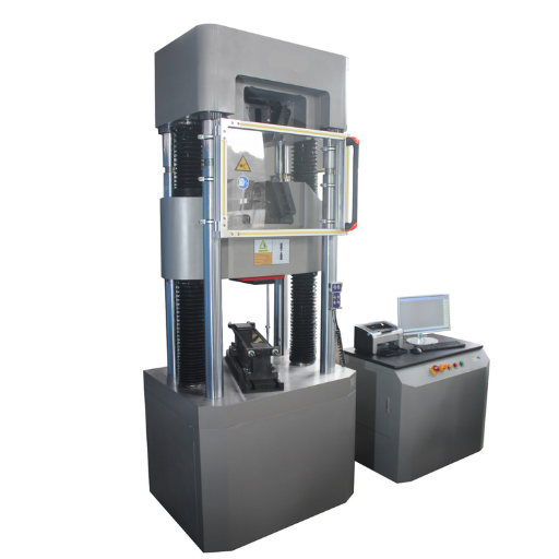
Hydraulic and electromechanical systems play pivotal roles in Universal Testing Machines (UTMs) by providing the force necessary to perform material testing with precision and accuracy. Hydraulic systems are commonly utilized for high-capacity testing scenarios, offering superior force generation and smoother load application over extended ranges. They operate by converting hydraulic pressure into mechanical force, making them ideal for tests requiring significant loads, such as tensile or compressive testing of heavy structural materials. Electromechanical systems, on the other hand, excel in low to medium load applications, delivering precise control over speed and displacement. They achieve this through motor-driven mechanisms, making them highly suitable for tests where accurate load rates and positioning are critical, such as flexural and fatigue testing. Together, these systems enhance the versatility of UTMs, enabling them to accommodate a broad spectrum of material properties and testing standards.
How Do Hydraulic Systems Function in a UTM?
Hydraulic systems in a Universal Testing Machine (UTM) function by utilizing pressurized fluid to generate and control the force applied during testing. These systems typically consist of a hydraulic pump, fluid reservoir, valves, and actuators. The pump generates the required pressure by driving hydraulic fluid into the system, while valves regulate the flow and direction of the fluid, ensuring precise control over the force application. Actuators convert the hydraulic pressure into mechanical motion, delivering the high force needed for testing operations such as tensile, compression, and shear tests. The high responsiveness and capacity of hydraulic systems make them ideal for testing materials that require large, consistent forces under strict testing standards. Their reliability and efficiency ensure accurate results across a wide range of applications.
Comparing Electromechanical vs. Hydraulic Systems
Electromechanical systems are precise, energy-efficient, and cleaner, while hydraulic systems are powerful, durable, and better for high-force applications.
|
Parameter |
Electromechanical |
Hydraulic |
|---|---|---|
|
Force Output |
Moderate |
High |
|
Precision |
High |
Moderate |
|
Energy Use |
Efficient |
High Consumption |
|
Maintenance |
Low |
High |
|
Cleanliness |
High |
Low |
|
Speed |
Moderate |
High |
|
Durability |
Moderate |
High |
|
Initial Cost |
High |
Moderate |
|
Operating Cost |
Low |
High |
|
Applications |
Light/Precise |
Heavy/High Force |
What Are the Testing Equipment and Fixtures Used in UTMs?
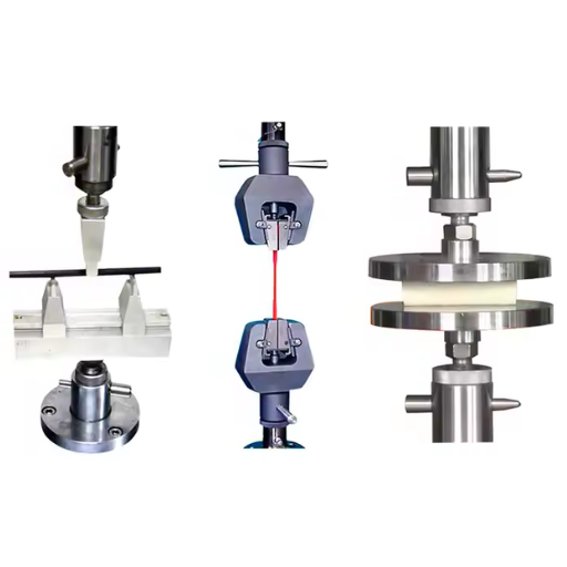
Universal Testing Machines (UTMs) employ a variety of testing equipment and fixtures to perform precise and reliable mechanical tests. Key components include:
- Load Frame: The load frame provides the structural foundation of the UTM, ensuring stability during testing. It houses the crosshead, which moves to apply the required force or displacement to the test specimen.
- Grips and Fixtures: These are used to properly secure test specimens in place. Grips may vary depending on the specimen type, such as wedge grips for metals, pneumatic grips for delicate materials, or specific fixtures for bending and shear tests. Proper selection and alignment are critical for obtaining accurate results.
- Load Cell: The load cell is responsible for measuring the force applied on the test specimen. It converts mechanical force into an electrical signal, allowing for precise quantification of load during testing. Load cells are carefully calibrated to ensure accuracy.
- Extensometers: Extensometers measure deformation in the test specimen, capturing elongation or compression across a specific gauge length. They are essential for determining strain and deformation-related metrics.
- Environmental Chambers: For tests requiring control of temperature or humidity, environmental chambers are integrated to simulate specific conditions, enabling material testing under environments such as extreme heat, cold, or moisture levels.
By leveraging these components, UTMs perform highly accurate and reproducible material tests for diverse applications.
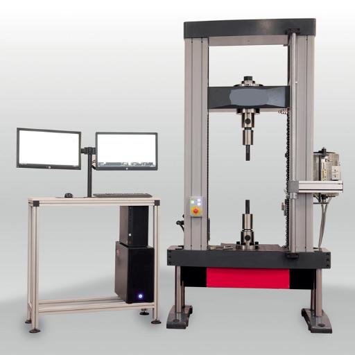
Understanding the Load Frame and Its Importance
The load frame is a critical structural component of a Universal Testing Machine (UTM), designed to provide the necessary mechanical stability and alignment during testing. It consists of rigid columns and crossheads, ensuring precise alignment and equal load distribution across the specimen. The load frame must exhibit high rigidity to minimize deformation during tests, as any frame distortion can lead to inaccurate results.
Key Technical Parameters of the Load Frame:
- Maximum Load Capacity: Typically ranges from 5 kN to 5,000 kN, depending on the application and testing requirements.
- Frame Stiffness: High stiffness is essential to avoid deflection under load; values are usually specified by the manufacturer to match testing precision standards.
- Crosshead Travel Distance: Determines the maximum elongation or compression that can be applied to the specimen, often adjustable depending on test type.
- Column Configuration: Most frames use a dual-column or four-column setup for improved stability and load alignment.
By maintaining strict control over these parameters, the load frame ensures the reliability and accuracy of material testing processes, even under complex loading scenarios.
Role of Grips and Fixtures in Ensuring Accurate Tests
Grips and fixtures are essential components in material testing as they ensure proper sample alignment and securement during testing. Below is a detailed list of their roles:
- Sample Securement: Grips hold the specimen firmly in place to prevent slippage or movement during testing, maintaining consistent results.
- Load Distribution: Fixtures facilitate even distribution of stress across the sample, reducing the risk of localized failure or uneven data.
- Test Customization: Specialized grips and fixtures are designed for different sample shapes, materials, and testing protocols, ensuring versatility across various applications.
- Alignment Control: Properly designed fixtures help align the specimen precisely with the load axis, minimizing measurement errors caused by misalignments.
- Prevention of Damage: Grips made from materials with appropriate hardness and surface treatments avoid damaging delicate specimens.
- Compatibility with Test Standards: Fixtures ensure compliance with industry standards such as ASTM or ISO by meeting the specific requirements of the test being performed.
- Adaptability to Environmental Conditions: Some fixtures are designed to perform reliably under extreme conditions, such as high temperatures or submersion, ensuring dependable test results.
By addressing these roles, grips and fixtures play an instrumental part in achieving accuracy and reliability in material testing.
How Does a Load Cell Work in a UTM?
A load cell in a Universal Testing Machine (UTM) functions as a force transducer, converting mechanical force into an electrical signal. When a force is applied to the load cell, it undergoes deformation, which is precisely measured by strain gauges attached to it. These strain gauges detect minute changes in resistance caused by the deformation, producing an electrical signal proportional to the applied force.
Key technical parameters for load cells in UTMs include:
- Capacity Range: Typically ranging from a few Newtons (N) to several hundred kilonewtons (kN), depending on the machine’s application.
- Accuracy: Commonly as high as ±0.5% or better to ensure precise measurement.
- Sensitivity (mV/V): Usually ranges from 2 mV/V to 3 mV/V, which determines the signal output per unit of input voltage.
- Non-Linearity Error: Typically less than ±0.03%, ensuring uniform measurement across the loading range.
- Temperature Range: Load cells in UTMs often operate reliably between -10°C to 50°C, though specialized models can accommodate wider ranges.
- Overload Capacity: Generally designed to withstand forces 150% or more of their maximum rated capacity to prevent damage.
By integrating a load cell with advanced signal conditioning electronics and calibration, the UTM achieves high-resolution and accurate force measurements for various testing scenarios.
How to Interpret Test Results from a UTM?
Interpreting test results from a UTM requires a systematic approach to ensure data accuracy and applicability. Begin by reviewing the raw data output, typically captured in force, stress, strain, or displacement values. Verify that the data corresponds to the calibrated parameters of the machine and aligns with the specific test settings, such as loading rate and specimen geometry. Next, analyze the stress-strain curve to identify critical material properties, including yield strength, ultimate tensile strength, and elongation at break. Ensure that environmental conditions during testing, such as temperature and humidity, are documented, as these can influence material behavior. Finally, compare the results against relevant standards or baseline data to evaluate compliance and performance. Proper interpretation relies on attention to both the machine’s precision and the context of the test parameters.
Analyzing Tensile Strength Results
When analyzing tensile strength results, I focus on comparing the recorded values, such as yield strength and ultimate tensile strength, against established industry standards like ASTM or ISO. This comparison allows me to determine whether the material meets the required specifications. I assess the elongation at break to understand the material’s ductility and its ability to deform without failure. Additionally, I meticulously consider the testing conditions—temperature, humidity, and machine calibration—as these factors can significantly affect the outcome. By cross-referencing results with baseline data and ensuring adherence to standards, I can confidently evaluate the material’s compliance and overall performance.
Evaluating Compressive Strength Data
To evaluate compressive strength data, I focus on the material’s maximum load-bearing capacity before failure under compressive stress. Using standardized test methods, such as ASTM or ISO protocols, I ensure precise specimen preparation and testing conditions. I analyze stress-strain curves to identify peak compressive strength and assess material deformation characteristics. Cross-referencing these results with expected benchmarks allows me to determine performance reliability and suitability for specific applications while ensuring strict compliance with industry standards.
Interpreting Deformation and Elongation Metrics
Deformation and elongation metrics are critical in evaluating a material’s ductility and overall mechanical performance. I assess deformation by measuring the dimensional changes a material undergoes under applied stress, focusing on elastic and plastic deformations. Elongation, specifically, is calculated as the percentage increase in gauge length after fracture relative to the original length. This metric provides insights into the material’s ability to withstand tensile forces before failing. By analyzing these parameters alongside stress-strain curves, I ensure an accurate understanding of the material’s behavior under load and its compliance with necessary performance requirements.
Reference Sources
-
- What is a Universal Testing Machine? – TestResources
- Complete Guide to Universal Testing Machines – Industrial Physics
- How Universal Testing Machines (UTMs) Operate – TensileMill CNC
- What is UTM machine: Types, Uses and Benefits – Testronix Instruments
- Top Universal Testing Machine in China
Frequently Asked Questions (FAQs)
Q: What is a UTM machine and what is its function?
A: A UTM machine, also known as a Universal Testing Machine, is designed to test the mechanical properties of various materials. It applies a controlled force to a test specimen to determine characteristics such as tensile strength, compression, and bending.
Q: What types of tests can be performed on a universal testing machine?
A: A universal testing machine can perform different tests like tensile strength testing, compression tests, bend tests, torsion testing, and peel tests, among others. These tests help in evaluating the strength and durability of materials.
Q: How does a universal testing machine apply force to a test specimen?
A: The UTM applies a controlled force to a test specimen using hydraulic or mechanical systems, allowing precise measurements of how the material reacts under stress.
Q: What is the role of a hydraulic power unit in a UTM machine?
A: The hydraulic power unit in a UTM machine provides the necessary power to apply force to a test specimen, enabling accurate and consistent testing applications.
Q: What is strain gauge technology and how is it used in a UTM?
A: Strain gauge technology is used in UTMs to measure the amount of deformation or strain a material experiences when force is applied. This data is crucial in assessing the material’s mechanical properties.
Q: What are the materials that can be tested using a UTM machine?
A: UTM machines are used to test a wide range of materials, including metals, plastics, rubber, textiles, and composites, to understand their performance under different stress conditions.
Q: How does a UTM provide testing solutions for different industries?
A: UTMs provide versatile testing solutions for industries such as construction, automotive, aerospace, and manufacturing by offering a range of testing applications tailored to specific material requirements.
Q: What is a materials testing machine used for?
A: A materials testing machine is used to test the mechanical properties of materials, such as tensile strength, elasticity, and hardness, to ensure they meet required specifications and standards.
Q: How does a UTM machine benefit quality control processes?
A: A UTM machine benefits quality control by providing accurate and reliable data on material properties, helping manufacturers ensure product quality and compliance with industry standards.
Q: What is the significance of tensile strength testing in a UTM?
A: Tensile strength testing is significant in a UTM as it determines the maximum stress a material can withstand while being stretched or pulled before breaking, providing crucial insights into its strength and durability.