When it comes to evaluating the structural integrity and performance of welded materials, the guided bend test stands as a gold standard in material testing processes. This article is designed to demystify the guided bend test, with a focus on mastering the machine itself—a critical tool in industries such as construction, manufacturing, and aerospace. Whether you’re a seasoned welding professional seeking to refine your techniques or a novice aiming to build a foundational understanding, this guide will provide a detailed exploration of the machine’s functionalities, preparation protocols, and advanced tips for ensuring accurate test results. By the end, you’ll be equipped with the knowledge needed to approach guided bend testing with confidence and precision.
What is a Guided Bend Test and How Does it Work?
A Guided Bend Test is a method used to evaluate the ductility and soundness of a welded joint. This test involves bending a prepared test specimen into a specific angle or radius to assess whether the material can withstand deformation without cracks or defects appearing on its surface. The specimen is placed in a guided bend testing machine, which ensures precise bending control according to the required testing standards. The results provide critical insights into the weld quality, helping to identify issues like incomplete fusion or porosity. This test is widely utilized in industries where weld integrity and structural performance are essential.
Understanding the Bend Test Process
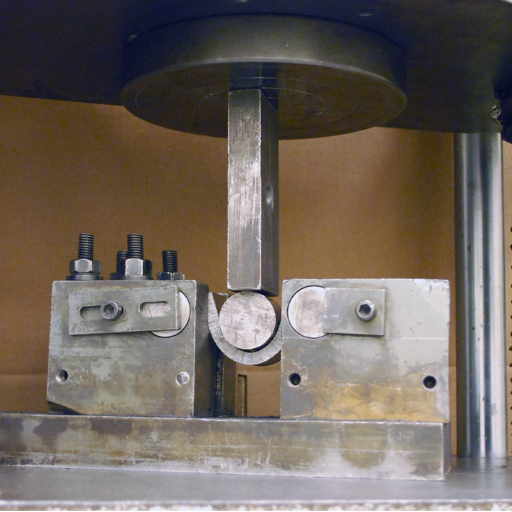
The bend test begins by preparing a specimen, typically a rectangular strip, cut perpendicularly to the weld seam to ensure accurate representation of the weld’s integrity. The specimen is then positioned in the bending apparatus with support rollers at specified distances apart, as defined by international standards (e.g., ASTM E190 or ISO 5173). Applying consistent force, the specimen is bent to a predetermined angle or until the specified radius of curvature is achieved. Inspectors examine the tension side of the bent specimen for surface defects like cracks, tears, or incomplete fusion. This detailed methodology ensures consistent assessments and provides valuable data for evaluating the overall fitness of materials and welds in critical applications.
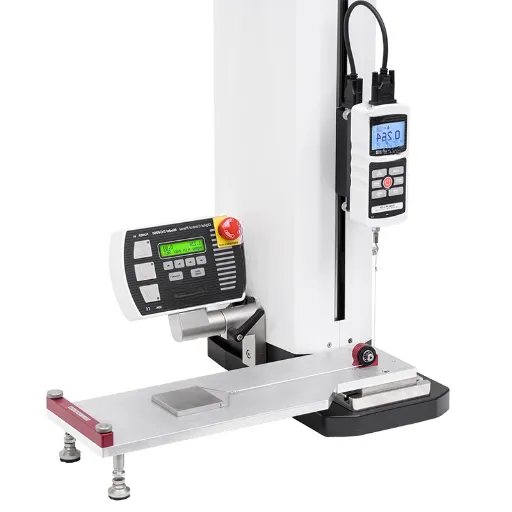
Key Components of a Bend Tester
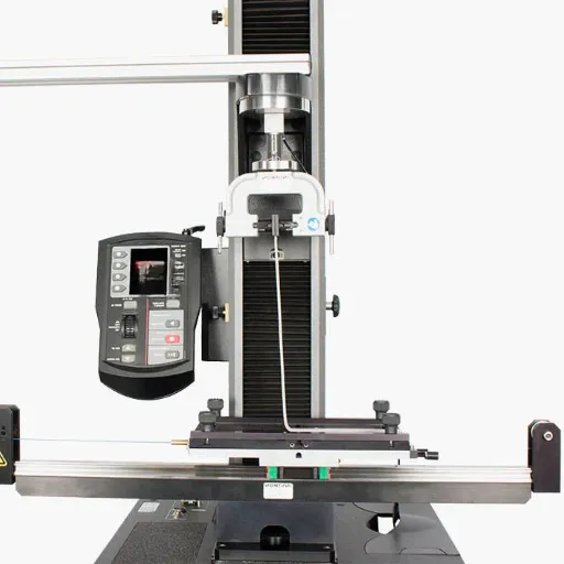
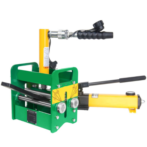
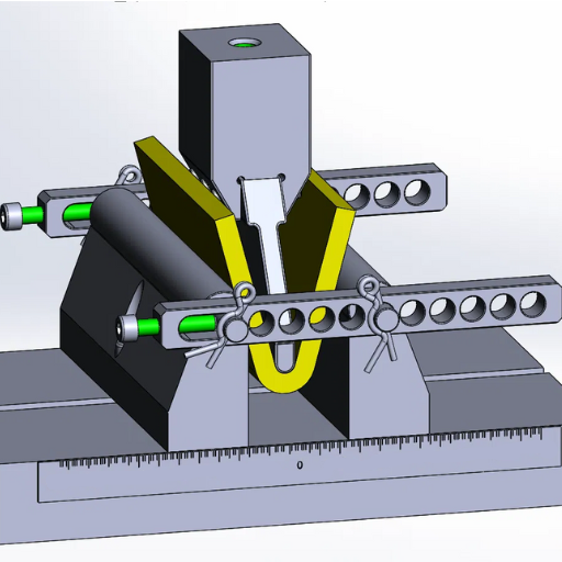
A bend tester is a precision instrument designed for assessing the ductility and integrity of materials through bending tests. Its components are engineered to ensure accuracy, repeatability, and compliance with established standards. The following are the key components of a bend tester, along with their specific roles and characteristics:
- Mandrel or Former
The mandrel, often constructed of hardened steel, serves as the central bending tool. Its diameter or radius directly affects the bending parameters and is selected based on test specifications. Common sizes for mandrels range from 1.5 mm to over 100 mm to accommodate diverse testing needs.
- Support Rollers
These adjustable rollers hold the test specimen in position and guide it during the bending process. The spacing between rollers can typically be configured based on the width of the specimen and test requirements, ensuring compatibility with various specimen sizes and materials.
- Specimen Clamping Mechanism
This mechanism secures the test material, preventing slippage or improper positioning during the bending test. High-precision clamping systems minimize error and ensure uniform force application.
- Load Application System
Many modern bend testers utilize hydraulic, pneumatic, or mechanical systems to apply force. These systems are engineered to produce consistent, adjustable force levels, which are typically measured in Newtons (N) or kilonewtons (kN), enabling precise control over bend angles and material stress limits.
- Angle Measurement System
An integrated system for measuring the bend angle is essential for ensuring that tests meet established criteria. These systems typically include digital readouts or laser-based angle sensors, allowing for angle resolutions as fine as 0.1 degrees for high accuracy.
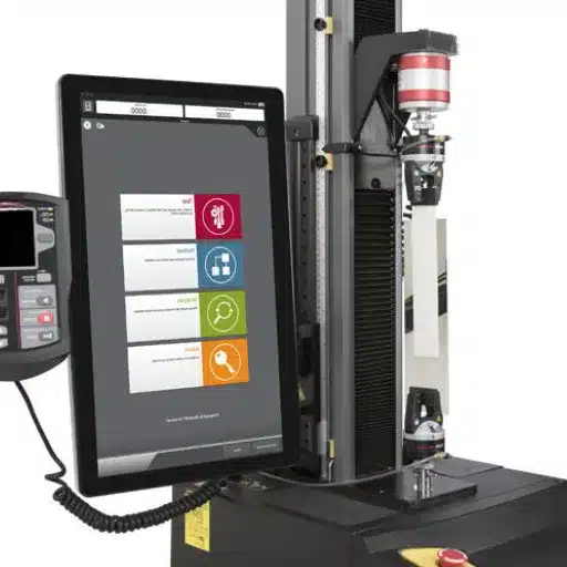
- Controller and Data Logging System
Advanced bend testers feature computerized controllers for managing test parameters, such as force, angle, and speed of bending. The data logging module stores results for post-test analysis, ensuring traceability and compliance with quality control protocols.
- Frame and Base
The frame and base provide structural support and stability during testing. Constructed from materials such as cast iron or reinforced steel, they are designed to withstand high loads and vibrations, ensuring consistent performance.
Each of these components plays a critical role in the proper functioning of the bend tester, allowing it to deliver reliable and accurate assessments of material properties. Modern advancements in design and automation have further enhanced the efficiency of bend testing, making it indispensable in industries requiring stringent material performance validation.
The Role of Weld Bend in Quality Assurance
- Structural Integrity Validation: Weld bend testing ensures that welded joints can withstand operational stresses without failure, verifying the structural integrity of the materials used.
- Defect Detection: It helps identify critical flaws such as cracks, porosity, or weak bonds in welded joints, which could compromise overall product safety and performance.
- Compliance with Standards: The procedure ensures adherence to industry and regulatory standards, guaranteeing that welded components meet specified quality thresholds.
- Performance Reliability: By evaluating welds under controlled stress scenarios, the test confirms that joints perform reliably in real-world applications, reducing the risk of unexpected failures.
- Optimization of Welding Techniques: Results from weld bend testing can provide feedback for improving welding processes and techniques, leading to superior and more consistent weld quality over time.
How to Use a Bend Test Machine Safely?
The following steps should be taken each time in order to effectively operate a bend test machine:
- Check on the Machine: Ensure that the machine is well calibrated, undamaged and intact in its capacity. Check upon the test sample too, that it’s dimensionally and otherwise compliant.
- PPE Use: Duty wear such as helmets, gloves, noise suppression, goggles, chinstrap shoes, etc. needs to be won with caution at alla safety measures.
- Correctly Fix the Cross Section to be Tested: Place the Cross Section under test in position correctly according to the instructions of the manufacturer. If not done correctly, this might affect the test results or result into damage of the equipment.
- Comply with Usage Directions: Make use of the machine in conformity with the appropriate standard usage procedures. Do not surpass any given load limits or cause the machine to press into anying inordinate stress force.
- Ensure Room is free of Objects: Ensure that no objects surround the machine while testing. Also, only those authorized should be present at the test site.
- Supervise the Test: Observe the test and consider any developments that could comprise a safety hazard. If anything unusual is noticed, change the course of direction of the test and stop the guided bend test machine.
- Carry out taming: The machine should be cleaned, checked, and services regularly to enable its safe use without any problems.
Setting Up the Guided Bend Equipment
To set up the guided bend equipment, I begin by carefully selecting the appropriate bending die and mandrel based on the material specifications and required bend radius. This ensures compatibility with the test parameters and desired outcomes. Next, I secure the specimen in the bending fixture, making precise adjustments to align it properly according to the specified dimensions. I then verify that all components are tightly fastened and that the equipment itself is calibrated to meet the procedural standards. Before starting the operation, I double-check the workspace for safety and confirm that the bending axis orientation aligns with the expected stress points. This meticulous approach minimizes errors and ensures reliable test results.
Safety Precautions When Operating the Machine
When operating the machine, I always wear the recommended personal protective equipment (PPE), such as safety goggles, gloves, and protective footwear, to mitigate potential risks. I ensure the machine is powered off during setup or maintenance to avoid accidental activation. Additionally, I verify that all safety guards are in place and functioning correctly before initiating operation. Regular inspections and adherence to the manufacturer’s guidelines are integral to prevent malfunctions and maintain safe working conditions.
Step-by-Step Guide to Performing a Bend Test
- Prepare the Testing Area
Ensure the workspace is clean, well-lit, and free from any obstructions. Verify that all required testing equipment, including the bending machine and specimen fixtures, are in proper working condition.
- Inspect the Specimen
Examine the material specimen for any visible defects or irregularities. Measure and record the dimensions of the specimen, ensuring it meets the standard requirements outlined by applicable testing protocols (e.g., ASTM or ISO standards).
- Set Up the Equipment
Secure the bending machine on a stable surface and install the correct die and punch size based on the material type and test specifications. Confirm that the alignment is precise to produce accurate results.
- Calibrate the Machine
Perform a calibration of the bending machine to validate force and displacement accuracy. Follow the manufacturer’s instructions to ensure the system is prepared to produce standardized data.
- Position the Specimen
Place the material specimen securely into the testing apparatus, aligning it precisely within the designated support points of the bending machine. Double-check the alignment to avoid introducing measurement errors.
- Initiate the Test
Start the bending process by applying a controlled load or force to the specimen at a measured rate. Monitor the display panel for real-time data, including force applied and the angle of deformation.
- Observe and Record Data
Continuously observe the behavior of the specimen, noting key changes, such as the formation of cracks or fractures. Record all relevant data during the test, including maximum force, bending angle, and any signs of failure.
- Conclude the Test
Once the test is complete, power down the machine and safely remove the specimen from the testing setup. Examine the specimen for permanent deformation, cracks, or breaks.
- Analyze Results
Compare the recorded data against the material’s predetermined specifications or standards. Document findings in the appropriate report format, including visual evidence such as photographs if necessary.
- Maintain the Equipment
After completing the test, clean and inspect the bending machine, ensuring all components are free from residue or debris. Perform routine maintenance to keep the equipment in optimal operating condition.
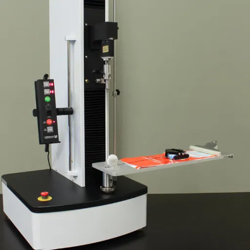
What Are the Applications of a 55 Ton Bend and Tensile Tester?
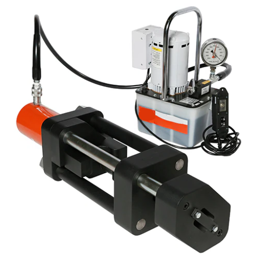
The 55 Ton Bend and Tensile Tester is primarily used in material testing applications across a variety of industries. It is widely employed in quality control and research laboratories to evaluate the mechanical properties of materials such as metals, alloys, and composites. Common applications include determining tensile strength, yield strength, and elongation under stress, as well as assessing the bending capabilities of materials. This equipment is integral to ensuring compliance with industry standards and specifications, particularly in sectors like construction, aerospace, automotive, and manufacturing, where material performance is critical to safety and functionality.
Industrial Uses of a Ton Bend and Tensile Tester
1.Material Quality Assurance: Ton bend and tensile testers are used to verify that materials meet industry standards for strength and durability, ensuring their suitability for specific applications.
2.Product Development: These testers play a critical role in research and development by providing precise data on material behavior under various forces, aiding in the creation of new materials and products.
3.Failure Analysis: By testing materials to their breaking point, these tools help identify weaknesses or points of failure, which is crucial for improving design and enhancing safety.
4.Compliance Testing: Industries such as aerospace and construction rely on these instruments to certify that materials conform to regulatory and safety standards before they are deployed.
5.Process Optimization: Ton bend and tensile testing data allow manufacturers to fine-tune production processes, leading to improved material performance and cost efficiency.
Testing Weld Joints with Precision
Precision testing of weld joints involves evaluating their mechanical properties and structural integrity to ensure reliability under operational conditions. Common methods include tensile testing, which measures the joint’s strength under tension, and bend testing, assessing ductility and defect resilience. Non-destructive testing techniques such as ultrasonic testing (UT) and radiographic testing (RT) are also widely used to identify internal flaws without compromising the weld. Advanced methods, like phased array ultrasonic testing (PAUT), provide detailed imaging for complex weld geometries. These analyses ensure compliance with industry standards, optimize weld quality, and ultimately contribute to safer and more efficient structures.
How Does the Bend Test Fixture Enhance Testing Accuracy?
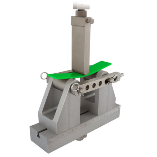
The bend test fixture enhances testing accuracy by providing a controlled environment to assess the ductility and soundness of materials, particularly welds. Its precise design ensures consistent application of force during testing, minimizing variables that could affect results. This standardization allows for reliable evaluation of material performance under stress, ensuring conformity with industry specifications.
Importance of Test Fixture in Bend Testing
The test fixture is a critical component in bend testing as it ensures the accuracy, repeatability, and credibility of test results. By providing a stable and uniform setup, the fixture eliminates inconsistencies caused by external factors or improper alignment, ensuring the force applied to the specimen is evenly distributed. This precision is essential for evaluating material properties like flexibility, ductility, and fracture resistance. Additionally, the test fixture complies with standard testing protocols defined by organizations such as ASTM and ISO, enabling results to be benchmarked globally. Its design directly influences the reliability of quality assurance processes, making it indispensable in applications ranging from structural engineering to manufacturing.
Adjustable Features of a Bend Test Fixture
The adjustable features of a bend test fixture typically include customizable span width, ensuring compatibility with various specimen sizes and shapes. Additionally, the supporting rollers or anvils can often be adjusted to accommodate different test standards or material dimensions. Some fixtures also allow the application angle or load rate to be modified for precise control over test conditions. These adjustments maximize flexibility and accuracy, enabling the fixture to meet diverse testing requirements across industries while adhering to global standards like ASTM and ISO.
What are the Key Differences Between Hydraulic and Electric Bend Testers?
Hydraulic and electric bend testers differ in their power source, control precision, maintenance requirements, operational noise levels, and typical use cases.
|
Key Parameter |
Hydraulic |
Electric |
|---|---|---|
|
Power Source |
Fluid Pressure |
Electric Motor |
|
Control Precision |
Moderate |
High |
|
Maintenance |
High |
Low |
|
Noise Levels |
High |
Low |
|
Use Cases |
Heavy-Duty |
Precision |
Comparing Hydraulic and Electric Systems
Hydraulic and electric systems differ in power source, precision, maintenance, noise, efficiency, cost, portability, sustainability, and typical applications.
|
Key Parameter |
Hydraulic |
Electric |
|---|---|---|
|
Power |
Fluid-Based |
Motor-Based |
|
Precision |
Moderate |
High |
|
Maintenance |
High |
Low |
|
Noise |
High |
Low |
|
Efficiency |
Moderate |
High |
|
Cost |
Moderate |
High Initial |
|
Portability |
Low |
High |
|
Sustainability |
Low |
High |
|
Applications |
Heavy-Duty |
Precision |
Choosing the Right Bend Tester for Your Needs
When choosing the right bend tester for my needs, I focus on a balance between precision, efficiency, and application requirements. If my priority is high precision for testing delicate materials, an electric bend tester is the optimal choice due to its precise motor-based operation, low noise, and sustainability. However, for high-force applications or heavy-duty materials, a hydraulic bend tester is better suited because of its robust fluid-based power and cost-effectiveness in initial investment. Additionally, I consider factors such as maintenance demands and portability. Electric testers require less maintenance and are more portable, whereas hydraulic testers, while less portable, provide the durability needed for heavy industrial applications.
Reference Sources
-
Bend Test Welding: A Guide to Passing Welding Certification – A comprehensive guide on the role of guided bend testing in weld qualification.
-
Bend Test Welding: A Guide to Testing Metal Welds – Explains the mechanical testing method for evaluating ductility and soundness of welds.
-
55 Ton Tensile Tester | Destructive Weld Testing – Details on equipment used for guided bend and tensile strength tests.
-
How to Pass Guided Bend Test on 6061-T6 Alloy – Insights into guided bend testing for specific alloys like 6061-T6.
-
Structural Integrity: Materials Testing | OpenLearn – A resource on various material testing methods, including guided bend testing.
Frequently Asked Questions (FAQs)
Q: What is a guided bend test machine?
A: A guided bend test machine is a versatile piece of equipment used to evaluate the ductility and soundness of welded joints by bending a test coupon to a specific angle. It is commonly used in welding labs and fabrication facilities to ensure compliance with standards like ASME and API.
Q: How does the guided 55 ton machine differ from other models?
A: The guided 55 ton machine is designed to handle test coupons with significant force, making it suitable for thicker materials. Its robust construction allows it to accommodate various diameters of mandrels, which is essential for testing different specimen thicknesses during bending.
Q: What role does the operator play in the guided bend test?
A: The operator is responsible for setting up the test coupon, selecting the appropriate diameter mandrel, and ensuring the machine operates correctly. The operator’s skill is crucial for obtaining qualitative results, as they must carefully monitor the specimen during bending.
Q: What is the significance of using a fischer accessory in a guided bend test machine?
A: A fischer accessory can enhance the functionality of a guided bend test machine by providing additional testing capabilities. It helps in achieving more precise results and may include components like a plunger or optional attachments for specific testing requirements.
Q: Can the guided bend test machine comply with military codes?
A: Yes, the guided bend test machine can be configured to comply with military codes, as well as other industry standards such as ASME and API. It is essential to select the appropriate accessories and settings to meet specific code requirements.
Q: How is a test coupon prepared for a guided bend test?
A: A test coupon is typically cut from a welded joint using a tool steel saw. The coupon’s edges must be smooth and free of defects to ensure accurate test results. The dimensions and thickness of the coupon are determined by the relevant standards, such as ASME section IX or API 1104.
Q: What types of bends can a guided bend test machine perform?
A: A guided bend test machine can perform various types of bends, including side bends, face bends, and root bends. The type of bend selected depends on the testing requirements and the specific characteristics of the welded joint under examination.
Q: Who typically uses a guided bend test machine?
A: Guided bend test machines are widely used by welders, quality inspectors, and engineers in welding labs, fabrication shops, and educational institutions. They are essential tools for testing the integrity of welded joints and ensuring compliance with industry standards.
Q: What is the importance of a diameter mandrel in a guided bend test?
A: The diameter mandrel is a critical component in a guided bend test, as it determines the bend radius during testing. Selecting the correct diameter mandrel is essential for accurate and reliable test results, which reflect the weld’s ability to withstand bending without cracking.