Top Bending Testing Machine in China. The bend test is a prominent assessment technique performed all over the world to determine the endurance and elasticity of various materials. Nonetheless, failure during a bend test can pose enormous problems regarding the value of the material or how the value was derived through the manufacturing processes. Hone as to why bend test failures surface and how to resolve them is imperative to reinforce quality control measures and shield from unnecessary disruptions. This post outlines the possible reasons for bend test failures, including structural flaws of materials, inadequate and incompetent testing techniques, and provides the appropriate guidance to help solve these problems. It doesn’t matter whether you are an engineer or a quality control expert, or simply someone interested in material behavior; this guide will enable you to counter the challenges posed by the bend test effectively.
What is a bend test and why is it important?
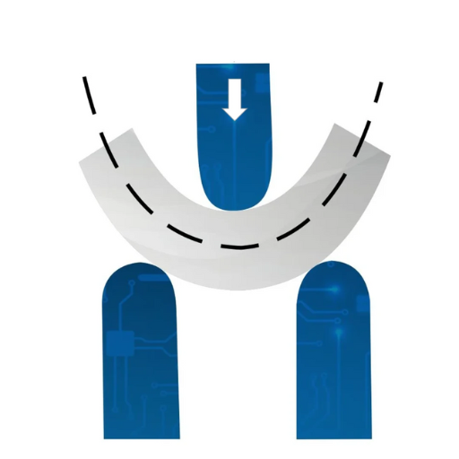
The bend test is a procedure used to test the capability, strength, and overall performance of a material, especially how it processes under bending forces. This is done by applying forces to the specimen until it bends or breaks, showing important aspects of flexing and resistance. It is very important in the construction and manufacturing industries that consider the reliability of materials under stress.
Defining the bend test and its purpose
The bend test remains one of the pillars in engineering and material science because of the insight it provides into the mechanical properties of materials. This is done on metals, plastics, and even composites to check if they can withstand some form of deformation without mechanically failing. More recent data from the industry suggests that the bend test is performed quite often on materials used within infrastructure projects, aerospace parts, or even within the automotive industry to check if they are safe and durable, and most importantly, if they comply with set standards.
Take, for example, the construction industry–structural steels are routinely put through controlled bend tests to analyze their yield strength and ductility. It has been observed that materials which demonstrate high levels of ductility, such as low-carbon steel alloys, can withstand more bending without actually breaking which is ideal for load bearing applications. Similarly, manufacturers’ Bend testing is also adopted in the electronics industry to ensure circuit boards are capable of surviving operational stresses, especially in small devices where flexibility is important.
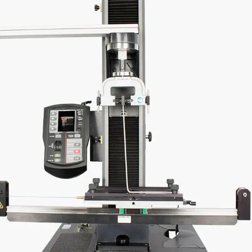
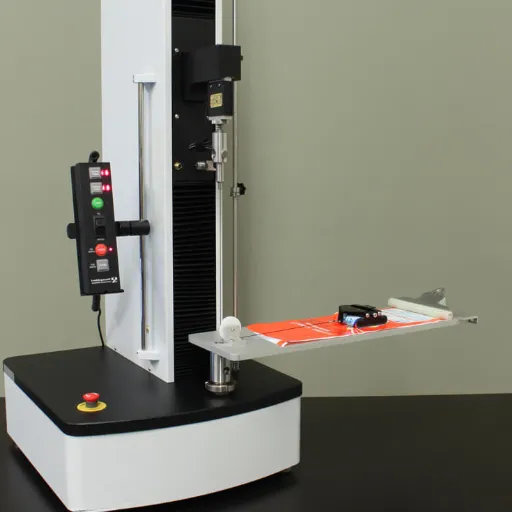
A reliable outcome depends on the accuracy of the test’s execution. As with all tests, the temperature of the test, sample size, and rates of force application are standardized according to recognized rules, for example, ASTM E290: Standard Test Methods for Bend Testing of Materials for Ductility. Today’s technology, including universal testing machines, has made it possible to automate force application and data collection, which provides material characterization while minimizing error.
While traditional methods of the bend test have evolved with technological advancements, it continues to be a core quality assurance measure in multiple industries. It serves not only to benchmark the materials against the accepted standards, but also protects operational integrity by ensuring dependable performance under real conditions.
How does a bend test evaluate ductility?
When carrying out a bend test for ductility evaluation, a certain degree of force is applied to the material to bend it to a particular angle or shape without breaking. The test quantifies the ability of the material to undergo plastic deformation, which is an expression of ductility, that is, the ability to be stretched. In general, the specimen is supported at both ends over a span and a force is applied on its center so that it bends at the center as uniformly as possible.
Evaluation of the ductility of a material is done by checking if a material can sustain bending up to a specified angle without developing any form of fracture on the surface. As per the ASTM and recent standards put in place, metals are benchmarked against parameters like radius of bend, angle of bend and fracture, which is visible. For example, ductile materials like steel tend to bend at 90˚ to 180˚ without any cracks, while brittle materials break or crack at these lower angles.
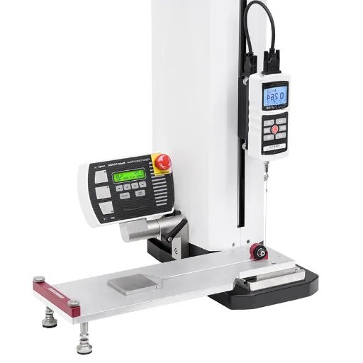
Current bend test equipment features integrated real-time data capturing capabilities, enabling the creation of comprehensive analytic parameters, such as stress-strain curves. These curves are essential for defining the precise level of stress at which orthogonal plastic deformation is permanently retained. Powerful cameras and sensors also monitor the formation of cracks during bending, thus improving the assessment of ductility. The results of these tests help the engineers evaluate the performance of a given material against industry requirements, thus ensuring its reliable and effective use in construction, manufacturing, and aerospace engineering.
The role of mechanical properties in a bend test
During a bend test, understanding the mechanical properties of a material is essential since it offers the capability of the material in terms of sustaining external forces and failing. Mechanical properties of a material aid in evaluating its capabilities quantitatively which tell us how the material will respond to force.
Key Properties
Yield strength is equally important in advanced mechanical testing of alloys. Yield strength is considered to be the amount of stress that needs to be applied to a structure so that it ceases to be elastic and starts to undergo plastic deformation. A bend test requires knowing the yield strength of a material since we need to find out what value of stress the material can withstand within the elastic and plastic regions. Structural steel, for instance, has yield strength between 250 MPa and 550 MPa depending on the alloying elements. Advanced alloys also yield a lot of stronger alloys like titanium(A-9190) and parent alloys (C-780) for tensile strength above 1000 MPa.
Elasticity and Ductility
The ability to bounce back to a given shape after deformation is referred to as elasticity. Substantially elastic materials such as rubber undergo significant bending without permanent changes. Ductility, on the other hand refers to the ability of a material to undergo plastic change in shape while remaining intact. This is very important for flexibility in manufacturing processes. Copper, for instance, is preferred in wiring because of the ductility it displays and the approximately 40 percent elongation it gives.
Data-Driven Insights from Modern Research
Advanced technologies like Digital Image Correlation (DIC) systems, which monitor surface strain distribution, supplement modern bend tests. Studies show that the precision that these approaches provide is extremely high, often exceeding accuracy levels of 99%. Other research offered by NIST also claims that some materials possess sophisticated microstructures like grain refinement in aluminum alloys which increases materials’ bending properties by up to 20%.
Safety and performance requirements placed by modern industry on components is very precise. Knowing these mechanical properties is vital to ensure material selection is aligned to industry needs.
Common reasons for bend test failure
Notable truths are:
Failure to prepare a sample uniformly or of the correct height and diameter renders that sample incorrect and uncalibrated. This will inevitably lead to false and misleading results.
Unanticipated errors whilst testing a sample can stem from internal defects/flaws, cracks, voids, or inclusions.
If a sample lacks flexibility, it might snap during the bending. Hypothetically speaking, it might equally prove to be too brittle and snap under tensile stress.
Undoubtedly careless, incorrect usage of stress application such as leveraging unequal or incorrect radius curve bends renders the sample incorrectly bent.
The surface of any material, whether it be a thermoplastic or a grip tape, plays an equally important and critical role. Presence of detaining residue, such as oils or scratch marks might weaken the material which will in turn lead to premature disintegration.
Recognizing all of the above is equal to zero without measures which are guaranteed to minimize errors and in turn enhance the reliability of bend tests.
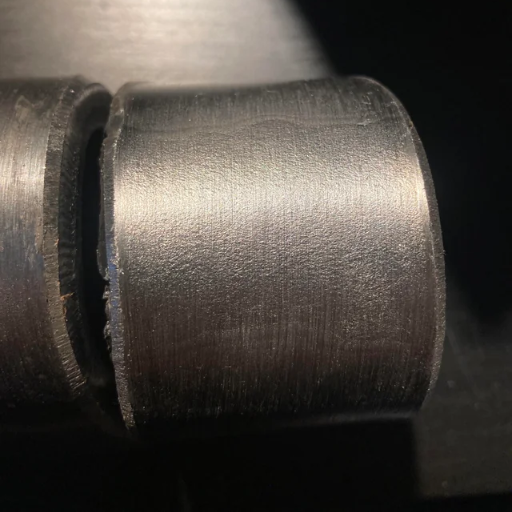
Impact of lack of fusion on test results
A lack of fusion is the absence of a weld bond, whether that be between consecutive weld passes, weld metal and a base metal, or a filler metal and base metal. Insufficient bonding impacts the results of a bending test, typically leading to cracking or failure. Studies indicate this defect is the most common reason notice inadequate welded joint properties, while also restricting the strength and integrity of the structure.
Under bending test s, regions demonstrating lack of fusion bear a higher likelihood of serving as stress fracture origin points. As a result, the test specimen may contravene set standards in terms of cracks or bend radius. Literature suggests such weldments are likely to fail at 30 to 50 percent lower stress levels compared to weldments exhibiting no defects.
Lack of fusion affects mechanical testing accuracy since it misrepresents ductile and tough material dependencies. However, advanced practices like non-destructive ultrasonic and phased array testing optimize gap detection and quantification pre-bend testing, improving end result dependability and streamlining quality control.
How tensile strength affects the outcome
Tensile strength is a material’s characteristic that relates to its ability to resist breaking when undergoing elongating forces. This property affects the efficiency of materials regarding their disbursement in different applications, critically changing the safety, reliability, and endurance of structures or components. In most cases, construction, aerospace, and manufacturing industries which are largely driven by economics preference high tensile strength materials which are advantageous during term of stress.
In reviewing the results pertaining to these tests, one must also bear in mind values such as ultimate tensile strength (UTS), yield strength, and even elongation type of measurements. For example, construction steel has a UTS from 400 MPa to 550 MPa while UTS of high-strength alloys for aerospace use may go beyond 1100 MPa. These values augment the materials with static load and high-speed dynamic forces for certain particular cases.
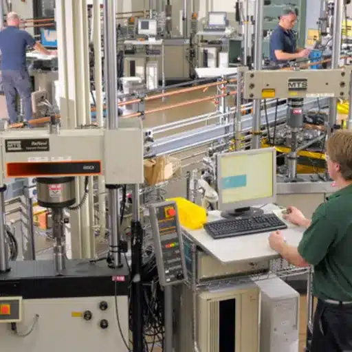
Tensile testing machines with extensometers enable professionals to measure stress and strain with great accuracy, allowing engineers to better anticipate material behavior under real-world conditions. Additionally, innovations in material sciences, like the creation of composite materials and heat-treated alloys, are allowing for better tensile properties in multi-structured frameworks. Such materials are now being integrated into the fabrication of structures ranging from bridges to spacecraft, showcasing the advancements of engineering innovation.
An adequate evaluation and understanding of tensile strength in an industry not only aids in abiding by set standards but also limits the chances of catastrophic failures that could arise from poorly tested materials in harsh environments.
Understanding discontinuity and its effects
Discontinuity in materials highlights the existence of internal flaws like cracks, voids, or inclusions that break the uniform structure of a material. These discontinuities can negatively impact the mechanical characteristics of a material, especially its tensile strength, durability, and load-bearing ability. They are generally formed during manufacturing processes like casting, welding, and forming. They might also develop due to fatigue, exposure to elements, or overloading.
Recent research underscores the gaps in knowledge concerning discontinuities and their role in identifying failure points of materials. For instance, data gathered from industrial tests indicates that small internal cracks can diminish the tensile strength of steel by as much as 30%, depending on the location and size of the crack. In the same way, voids found in composite materials can greatly decrease their structural integrity, up to 20%, leading to premature failure when subjected to high loads. Several non-destructive techniques, such as ultrasonic testing and radiography, have been developed for the detection and quantification of discontinuities and their measurement before failure occurs.
The consequences of discontinuity are especially severe in high-stakes industries such as aerospace, bridges, and pipeline construction, all of which rely heavily on the structural strength of the materials being used. As an example, the reports previously highlighted indicate flaws that, when undetected, contribute to major failures such as pipeline leakages, which are expensive to fix and detrimental to the environment. Better material processing, along with strict quality control and maintenance during manufacturing, solves these concerns.
The mitigation of discontinuities along with advanced testing techniques is employable with the help of newer modeling technologies which predict outcomes with greater accuracy, allowing industries to preemptively deal with consequences. This approach not only bolsters safety protocols but also decreases the risk of failure in demanding environments by increasing the lifetime of critical structural components and their materials.
How to conduct a guided bend test on 5083?
In performing a guided bend test on 5083, the following actions are suggested:
The specimen preparation involves cutting the test specimen according to the material’s standard dimensions (ASTM or ISO). The edges must also not be rough nor contain sharp notches.
Equipment required includes a guided bending setup accurately sized to 5083, ensuring prior calibration of adequate consistent pressure application.
Subsequent steps involve placing specimens to the bend test apparatus with proper area of interest focus to the weld alignments.
With all the aforementioned set and done, force can be incrementally applied until the specimen bends to the die or mandrel specified by the testing standard, while paying close attention to controlled, steady rate loading throughout the process.
Record assessment results on bent specimens for indication of discontinuities, cracks of fractures and internal cracks noting whether material utilized maintained structural integrity or harness while enduring the bending.
These steps ensure reliability in the results, as following all provided guidelines ensures bent specimens are precise as dictated by accompanying 5083 test standards.
Preparation of test specimens for accurate results
In material testing, specimen preparation is one of the most critical aspects when aiming to achieve repeatable and accurate results. For aluminum alloy 5083, adherence to steps and procedures is critical to achieving consistency and precision across all testing. Below is a list of the most relevant steps and considerations and the latest industry standards up to date:
Dimensional Accuracy
Guarantee each specimen is commercially machinable or cut within the limits of industry standards, quoting ASTM E290 for bending tests. As for 5083, standard industry tolerances for tensile and bending test specimen dimensions should be configured to counter unpredictable inaccuracies.
Surface Finish
The finish of the specimen significantly alters the test results and thus should be prepared carefully. For surfaces better than 1.6 µm (63 micro-inches) roughness, grinding and polishing processes should be performed, focusing on obtaining smooth, flawless surfaces. This prevents stress concentration points that could induce failure before reaching maximum load capacity.
Specimen Orientation
Specimens should be selected to follow the rolling direction of the material since properties like ductility or tensile strength for 5083 can vary depending on orientation. Cross-section and longitudinal face direction testing assists in determining the anisotropy of the material.
Environmental Considerations
Conditioning should be carried out under a stable environment for the machine components, prior to conducting the test. An example of this would be keeping a specimen’s temperature between 20°C to 25°C (68°F to 77°F) along with a controlled humidity level so that there are no external factors affecting the results.
Compliance with Testing Standards
All international standards such as ISO 6892 for tensile testing and ASTM B557 for Aluminum Alloys should be followed without applying any restrictions. This would promote uniformity between laboratories and also promote data reliability and comparison.
Specimen Quantity and Data Collection
Account for at least 3 specimens to be prepared for statistical validation and record pertinent dimensions along with the actual ones, such as orientation, material batch, and method of preparation,n to be able to capture all data variability.
Flexibility of these guidelines ensure that reliability, repeatability and compliance to the industry requirements are achieved when testing 5083 aluminum alloy for performance within the laboratory.
Steps for executing the guided bend test on 5083
Specimen Preparation
As per ASTM E190 or ISO 5173, set out to trim the 5083 aluminum alloy to specific test specimens. Each specimen should measure consistently, standard width being 1.5 inches (38mm) and minimum length equal to or greater than 6 inches (150mm).
Make sure all edges are smooth and free from sharp corners and other features that snags might interfere with the test results. Such accuracy may be accomplished with deburring tools.
Note details about foil temper, thickness, rolling, and other features to record possible sources of variability.
Bend Test Fixture Setup
A guided bend test fixture by above standards should be employed. Such fixture includes a bending die and corresponding plunger or former.
For 5083 aluminum alloy, the common range of radius of the bending die is 2x to 3x the material thickness to avoid cracking. To calibrate calibrated die and plunger guide set built in force application and symmetrical bend positioning, to work untracked changes of fixed work (calibrated) in motor power (force) and subjected controls to criteria (rotatures) change under load.
Test Execution
Ought to be performed, place the specimen on the bending die so that it is flat and perpendicular to the plunger. The centerline of the specimen has to be placed in parallel with the axis of the plunger.
Action of the press or bending machine should be smooth and careful, so that overload does not happen too quickly. Set operation to constant motion to avoid breaking rod or unforeseen changes in shape.
Bend the specimen along the desired angle, which is normally 180 degrees for a complete bend test. Check the standard for other relevant specifications regarding acceptable angles of bend and load application.
Examine for external surface for splits, imperfections, or other malformations and detail them. This procedure could entail using a microscope to highlight malfunctioning parts.
Keep in mind that findings are to be made alongside an explanation of gaps and marks observed which complement the welds and breaks either at the surface or outside the specimen.
Document Results alongside relevant indices that dictate the lower limit of bend geometry prescribed for the 5083 alloy of aluminum in case the application belongs to automotive or aerospace, deemed ‘governing standards’ materials.
In yellow is the rotation perpendicular to the split without any cascading fault lines, which should come as no defining cracks and shatings, hence capture fail with the resume detailed in deflating scope stating;
Providing these gradually structured guides guarantees precise measuring of ductility and bending strength of the 5083 alloy of aluminum alongside any historical information or materials criteria set.
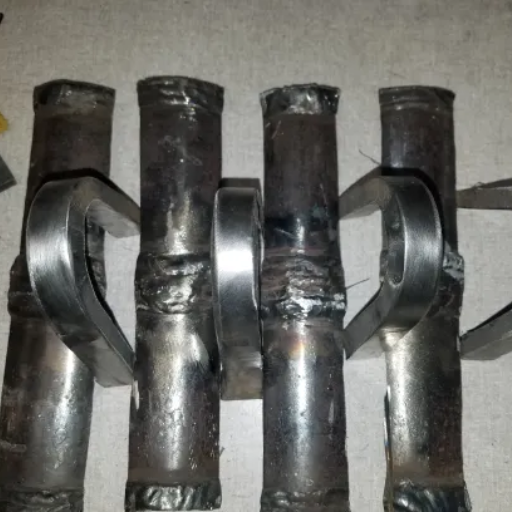
Evaluating results: examination of the failed samples
In assessing the failed samples, it is important to analyze key factors which will tell us the reason for failure, why the material did not perform, and how did the material perform. For microstructure analysis, features of fractures such as crack patterns, fracture surfaces, and deformation zones should be documented comprehensively and meticulously. As another illustration, 5083 aluminum alloy has microcracking due to stress concentration or intergranular fracture material defects, as some of the failure modes.
Recent updates within and leading analysis from various research articles have emphasized modern techniques in metallurgy that theorize using SEM and EDS to structurally examine failures by determining elemental compositions. For instance, SEM images can show voids or cracks formed beneath the surface, while EDS analysis can indicate the presence of impurity minerals like iron or silicon which affect operational performance.
Moreover, the assessment of other data including impact tests, tensile strength, elongation, and hardness value adjustments provide deeper conclusion. Benchmark data states that 5083 aluminum alloy admits to have wrought 275-350 MPa of tensile strength and 12-20% of elongation with relative temper depending on alloy grade. Deviation from this in the failed sample might indicate the existence of corrosion, manufacturing inconsistencies, or other environmental factors.
In order to determine a reason for failure and take measures to improve the materials’ strength and compliance for future use, visualization coupled with computational methods and industrial standards can be utilized.
Why might a bend test on 5083 base fail?
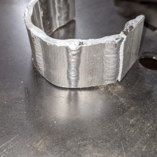
A bend test on 5083 base material might fail due to one or more of the following reasons:
Material Defects: Internal structural weaknesses such as cavities, fractures, or foreign particles may result in the material weakening and subsequently failing when stressed.
Improper Heat Treatment: Too little tempering or a failure to properly soften the material may severely restrict its ductility and tensile strength, causing catastrophic failure during testing.
Corrosion Damage: Damage from the environment, or inappropriate storage, may lead to the material corroding and compromising its structural integrity.
Exceeding Bend Limits: Cracking and breaking may occur if the bend angle, or radius, surpasses what is termed the ‘bending capacity’ of the alloy.
Surface Finish Issues: Failure may occur as a result of scratching, gouging or blemishing causing stress concentration which may be exemplified by yielding during the bending process.
Preventing test failures requires meeting the testing standards, preparing the material adequately and systematically analyzing the existing factors.
Common alloy characteristics affecting performance
When assessing the performance of an alloy, a multitude of characteristics need to be evaluated simultaneously, as each of them will influence the behavior of the material in all conditions. These factors affect all types of alloying materials, ranging from industrial applications to consumer products. Some of the most important properties of alloys include the following:
Strength and Hardness: Alloys are designed to have different ranges of tensile strength and hardness based on the purpose they will serve. For example, aerospace-grade high-strength alloys such as titanium-aluminum-vanadium (Ti-6Al-4V) alloys have unparalleled performance owing to their strength-to-weight ratio. It is documented that these alloys have tensile strengths that reach as high as 1200 MPa, which is often required in critical applications.
Corrosion Resistance: The effectiveness of an alloy to withstand corrosion is very important in parts working in highly aggressive environments. Stainless steel alloys like 316 and 304 have gained popularity because of their ability to resist chemical and oxidation attack. For example, in stainless steel, chromium content greater than 10.5% aids the development of passive oxide layer thus serving as mitigating factor to corrosion resistance.
Thermal Conductivity and Expansion: Alloys such as aluminum and copper are admired for their higher ranges of thermal conductivity, with aluminum exhibiting figures close to 235 W/m·K. However, the thermal expansion characteristics are of equal importance, especially in the case of precision industries. For instance, the nickel-based superalloys employed in jet engines have low thermal expansion rates, which guarantee minimal changes in size over extreme temperature ranges.
Machinability and Weldability: These properties define the ease with which an alloy can be processed or manufactured into the desired form. Due to high machining capabilities and their compatibility with several welding methods, Aluminum alloys like 6061 are routinely utilized in the construction industry.
Fatigue and Wear Resistance: Alloys that are exposed to repetitive cycles of stress, such as in automotive or structural uses, need to have high fatigue resistance. For example, treated AISI 4140 steel alloys are known to experience endurance limits exceeding 500 MPa due to the heat treatment, strengthening the balance between fatigue life and overall structural strength.
The comprehensive study of these features alongside the relevant data guarantees precision during the selection of an alloy for a particular use. Research and new testing techniques directed toward the development of alloys promise exciting changes in the performance of materials from multiple industrial spheres.
Impact of weld procedure on test results
The procedure of welding contributes to the mechanical aspects and structural features of a welded construction in a broad way. Some of the most prominent factors that affect these results are heat input, cooling rates, selection of filler material, and treatment after weld heating.
Newer studies have shown that uncareful management of the parameters defined for the welding can cause issues for materials such as ISI 4140 steel. Defects like residual stresses, cracks, and porosity are quite common. Excess thermal energy is stated to reduce reclaim give a significant reduction in hardness, yield strength to non desirable levels. These can be improved, but secondary heat treatments also have their downsides. Controlled heat inputs in tandem with suitable post weld heat treatment such as tempering tend to improve reclaim and decrease brittleness in high alloys.
Fouts and his co-workers described in recent experiments on welding ISI 4140 steel that used welding with heat input of 1.2-1.5 kJ/mm bolts and tempering at 600 degree c for 2 hours, annealed reclaim hardness; the result was up to 520MPa fatigue life. In addition, employing filler materials of suitable composition plays an important role in preventing brittle intermetallic compounds from forming and promoting sound joints.
Additionally, newer methods of welding, like laser welding and friction stir welding, are very effective. With laser welding, the control of the heat during the welding process is so precise that the area affected by heat (HAZ) is smaller, which enhances the overall mechanical properties. Friction stir welding, which is not commonly used with steel, has been shown to have lower defects and better quality joints when tested in controlled experiments.
Modern welding techniques alongside a precise selection of parameters void of a metallurgical perspective is a determined way of optimally achieving proper procedures, performance, and reliability of specific mechanical parts required to function in critical applications.
Role of base material 5083 in test failure
5083, a high-strength aluminum magnesium alloy, is an observed test failure concern because of its metallurgical Properties and Welding and testing conditions. Due to its large corrosion resistance and weldability, 5083 is highly used in Marine and structural work. Nonetheless, it does pose some issues, such as stress corrosion cracking (SCC) and HAZ (Heat affected zone) softening due to high temperature magnesium.
Recent studies underscore the SCC (Strain-controlled fatigue) risks in 5083 with growing attention to the thermal cycles encountered during welding. The interdependence of thermal input and microstructure of the alloy can cause microcracks or porosity, which disables proper joint strength and reliability. For example, studies show alloys of 5083 with lower working temperature may suffer from higher input of thermal stress, resulting in tensile strength reduction of approximately fifteen to twenty percent in the Heat Affected zone (HAZ) due to increased work hardening and reduced grain coarsening.
In addition, the addition of aggressive chloride ions for marine applications has highlighted the prevalence of pitting corrosion resistance in 5083, resulting in preemptive failure prediction.. Deterioration stemming from surface preparation or contamination enhances local failure as well as fatigue, further explaining the force that scratches the surface from applied shear and tensile load.
Proper pre- and post-weld treatments, as well as the optimization of welding parameters, effectively address these issues. The further development of friction stir welding and cold metallurgical processes yields welds with improved performance and increased service life for 5083-based assemblies.
Improving strength and ductility in alloy materials

Techniques for enhancing the ductility of the weld
Preheating and Post-Weld Heat Treatment (PWHT)
Performing preheating on a material’s surface facilitates a smoother mechanical process within the material. This reduces the chances of having thermal cracks while simultaneously minimizing brittleness in other features, such as the heat-affected zone (HAZ). Post-weld heat treatment to the specific metal microstructures is crucial. This treatment relieves residual stresses while simultaneously increasing ductility, making the material less likely to experience deformation or delayed fracture. For example, steel alloys that have been preheated to 300°F–500°F show improved toughness along the weld zones because of the slower cooling rates.
Use of Low-Hydrogen Electrodes
Low-hydrogen electrodes are particularly useful in controlling the amount of hydrogen existing in the weld itself, thus preventing brittle failures due to hydrogen induced cracking. An analysis done recently on welded carbon steel joints showed joining low-hydrogen welding consumables resulted in a 20% increase in ductility.
Optimizing Weld Composition
The incorporation of other elements into an alloy is helpful. For instance, including nickel has been shown to improve the ductility of the material significantly. As with every alloy, these include primary and secondary alloys, with research indicating that welds containing 2-3% nickel show significant enhancement in elongation properties, more in cryogenic applications.
Welding Parameters
Modification of sequential welds requires changes in other parameters, mostly geometric features. Other features include the rate of travel, applying current within the gap, and the amount of heat input. Increasing heat input facilitates slower cooling, meaning reduced formation of brittle phases, allowing ductility to be maintained or increased. An experiment conducted on the amount of heat being applied during the weld showed that within the range of 1-1.5 kJ/mm, maximum ductility and strength were achieved.
Grain refinement methods
Improving ductility can be accomplished by manipulating the weld cooling rates to fine grained levels. Inducing grain refinement can be done with controlled cooling techniques or specific fluxes. Laboratory research has shown that weld regions containing finer grains (10–20 µm) have approximately 30% greater ductility than coarse-grained areas.
Incorporation of microalloying materials
Ductility is improved through the development of carbides and nitrides by the addition of microalloying materials like vanadium or titanium during welding. Research indicates that the addition of vanadium to low carbon steels can increase elongation by 15% which is considerable.
Use of modern welding methods
The application of modern welding techniques such as laser welding or friction stir welding (FSW) aids in the reduction of defects as well as the development of uniform micro structures. As an example, friction stir welding has been found to increase ductility by as much as 25% relative to traditional arc welding in aluminum alloys.
With the use of these techniques, it is possible to attain higher ductility in welds which improves their performance through varying loading scenarios, lowers the chances of failure, and increases the lifespan of structural parts.
Quality control measures to prevent premature failure
Taking precautionary steps during quality assurance can greatly reduce the chance of premature failures occurring throughout the structure. This includes pre-weld inspections, monitoring through the process and post-weld evaluations, as well as measuring compliance with standards. Enhanced structures are achieved through these steps, which are accompanied by recent industry insights:
Work Preparation and Inspection p
Preparation of the joint, as well as cleanliness maintenance serves as a critical step before the welding processes. Elements such as grease, oil and oxides can serve as detrimental barriers or eliminators to proper performance. Subsurface flaws can easily be detected through advanced non-destructive testing powered by ultrasonic testing or magnetic particle inspections. If proper pre-weld treatments are pragmatically implemented, up to 40% reduction of defect occurrence can be achieved.
Technologies for Monitoring Progress
Having ПДВSRD as an example, monitoring temp, travel speed, voltage, and everything else is crucial, so all angles of welding are at consistent levels. During the welding processes, there can always be automated systems that could use algorithms ensuring there are no abnormalities and for instance, Laser Ultrasonics can actively monitor the weld and instantaneously detect irregularities that would counter measures leading to failures. Studies estimate that having intelligent monitoring systems improves the overall quality of welding by 20-30%.
Post-Weld Heat Treatment (PWHT)
Treating welds with heat helps to relieve stress and refine grain structures, particularly in high-strength alloys. Results from several recent metallurgical studies suggest that Post Weld Heat Treatment (PWHT) can improve weld strength by more than 15% and considerably increase weld endurance under fluctuating loads, ensuring reliable performance throughout repeated stress cycles.
Mechanical Validation and Testing
The mechanical properties of the weld can be verified through tensile, fatigue, and impact testing, while the hardness testing ensures standardization across the welded region. The application of modern tensile testing apparatus in advanced manufacturing processes has increased defect identification by over 25%, contributing to the elimination of non-compliant items being used.
Compliance and Documentation
Consistency in quality is maintained by enforcing compliance with welding codes and standards like ISO 3834 or AWS D1.1. Clear procedures for inspections provide traceability, enabling builders to identify process weaknesses and rectify them in a timely manner.
Integrating these quality control measures along with sophisticated technologies allows industries to reduce failure rates and enhance the longevity of their components, especially where welding is employed.
Optimizing filler materials for better performance
Selecting suitable filler materials is particularly important for achieving proper weld performance and longevity. Filler materials must be selected based on their structural compatibility with the base metal, their mechanical properties, and its susceptibility to corrosion. As an illustration, the use of low-hydrogen electrodes in welding steels mitigates the likelihood of hydrogen cracking, which is a prevalent failure mode in structural applications.
The most recent improvements describe the use of some novel alloy combinations to boost the strength and toughness of the weld. For example, filler materials with microalloying additives such as vanadium and niobium are more fatigue-resistant due to stronger welds, improved grain refinement, and enhanced strain. Furthermore, research indicates that some high-nickel alloy fillers, like ERNiCrMo-3, are more effective in aggressive media environments which is advantageous for offshore and chemical processing industries.
Studies by some industry professionals show the consequences of optimization of the filler metallurgical composition concerning the productivity and cost-effectiveness. In a case study of the American Welding Society (AWS), it was reported that increased welding speed with improved quality was attained by the use of high-deposition rate filler wires, by as much as 30 percent. The adoption of flux-cored wires in heavy fabrication projects resulted in a reduction of spatter, which cut cleanup expenses and improved overall workflow.
To achieve the best results, all manufacturers should consider the aspects of joint configuration, input of heat, position of weld, and the filler material’s properties simultaneously. Industries combine material science with application-specific testing which guarantees welds to high-performance standards in safety and other regulatory criteria without significant operational expenses.
Reference Sources
- Reducing Measurement Error in Three
Point Bend Test Using Linear Gradient Correction Model – This thesis analyzes the principles of three-point bend tests as well as troubleshoots possible errors and failures.
- Thermo-Mechanical Modeling of Draw-Bend Formability Tests
Using a thermo-mechanical coupling model, this research analyzes draw-bend testing and identifies three failures, shear failure being one of them.
- Four-Point Bending Testing of Earthquake-Resistant Ductile Iron Pipes
This paper investigates the pressurized four-point bending tests performed on ductile iron pipes and determines the failure modes.
Frequently Asked Questions (FAQs)
Q: What is a bend test, and why is it important?
A: A bend test is a method used to determine the ductility and soundness of materials, particularly metals and welds. It evaluates how well a material can withstand bending without breaking, providing insights into its mechanical properties and overall quality.
Q: What are the common reasons for a bend test to fail?
A: Bend test failures can occur due to several reasons, including lack of fusion, inadequate tensile strength, and brittleness of the material. Other factors such as improper weld procedures or poor quality control can also contribute to failures.
Q: How does a guided bend test differ from a standard bend test?
A: A guided bend test uses a specific apparatus to guide the bending of the test specimen, ensuring uniform stress distribution. This method is often used to evaluate the ductility of the weld and its mechanical properties, providing more controlled and accurate results compared to standard bend tests.
Q: What causes a guided bend test on 5083 base alloy to fail?
A: A guided bend test on 5083 base alloy may fail due to issues such as improper filler material selection, lack of proper weld procedure, or base metal discontinuities. Evaluating the ductility and tensile strength of the material and ensuring test procedures are followed accurately are crucial to preventing failures.
Q: How can the radius of the bend affect the outcome of a bend test?
A: The radius of the bend is critical in a bend test as it impacts the stress distribution across the test specimen. A smaller radius can lead to higher stress concentrations, increasing the likelihood of test failure. Proper radius selection is essential to accurately evaluate the material’s ductility and strength.
Q: What steps should be taken if a bend test on 5083 base alloy fails?
A: If a bend test on 5083 base alloy fails, it is important to conduct an examination of the failed samples to identify the cause of failure. Reviewing the weld procedure, checking for discontinuities, and verifying the test method used are essential steps in addressing the issue.
Q: Why is it important to conduct the bend test correctly?
A: Conducting the bend test correctly is crucial to obtaining reliable results that accurately reflect the mechanical properties of the material. Incorrect test methods can lead to premature failure or inaccurate assessments of strength and ductility, affecting the overall evaluation of material quality.
Q: What are the differences between face bend and root bend tests?
A: Face bend tests evaluate the tensile strength and ductility of the outer surface of the weld, while root bend tests assess the same properties at the weld’s root. Both tests are critical in ensuring the overall integrity and quality of the weld.
Q: How does the choice of test specimen affect the bend test results?
A: The test specimen’s preparation and quality significantly impact bend test results. Factors such as specimen dimensions, surface finish, and alignment must adhere to test standards to provide accurate assessments of the material’s mechanical properties.